30 NFS2-3030 Operations Manual — P/N 52546:A 11/29/2005
Operation of the Control Panel Pre-alarm Event
2.3.4 Interpreting Type ID Codes
The Type ID code that displays in a point trouble message is related to the type and function of the
point that initiates the trouble. For example, a monitor module with a
PULL STATION Type ID code
means that the monitor module connects to a manual pull station. If the Type ID code is unfamiliar,
refer to Appendix A, “Software Type ID Codes”, on page 63. This appendix is an alphabetical list
of Type ID codes and an explanation of each.
2.4 Pre-alarm Event
The Pre-alarm function is used to receive an early warning of potential or incipient fire conditions.
The Pre-alarm function provides one of two settings as follows:
• Alert – a non-latching setting that causes a Pre-alarm when a detector reaches its programmed
Pre-alarm sensitivity threshold. Non-latching means the condition will automatically restore to
normal once the detector’s sensitivity readings drop below its Pre-alarm threshold.
• Action – a latching setting that causes a Pre-alarm when a detector reaches its programmed
Pre-alarm level. Latching means the condition will not restore itself to normal once the
detector’s sensitivity readings drop below its Pre-alarm threshold. The panel must be reset.
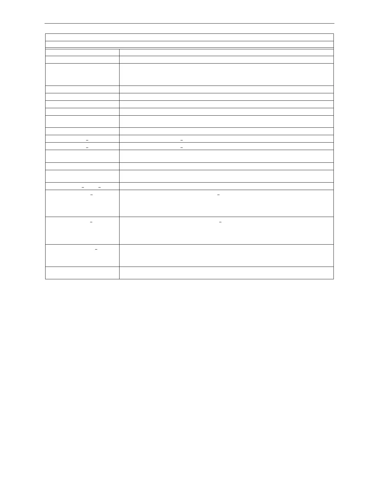
NVRAM BATT TROUBLE Battery backup and/or clock backup is low. Replace battery.
NO DEV. INST ON L1 No devices are installed on the system.
NO POWER SUPPLY INST The AMPS-24 (main power supply) AC fail address (base plus one) has not been correctly entered or the loop
is not installed. The AMPS-24 is not configured for “Trouble Reporting”. All four of the main power supply
addresses are not programmed for MOD TYPE=Monitor and/or TYPE CODE LABEL=Power Monitor and/or
FLASHSCAN=PS Mon.
PANEL DOOR OPEN The panel door is open.
POWER SUPPLY TROUBLE There is a communication failure with the DAA onboard power supply. Call Technical Services.
PRINTER OFF LINE Communication loss with printer. Restore power and/or printer’s online status.
PRINTER PAPER OUT Add paper.
PROGRAM CORRUPTED The database that houses the panel’s programming is corrupt. It must be re-downloaded, or all programming
must be cleared and re-entered. Service required.
PROG MODE ACTIVATED A user is currently using the panel’s programming menus.
REMOTE DISPLAY x
NO ANSWER The remote display at address x is not responding.
REMOTE DISPLAY x
TROUBLE The remote display at address x is in trouble.
REMOTE MIC TROUBLE The DVC’s remote microphone is in trouble. It is installed and supervised, but no signal is coming from it.
Investigate and fix.
SELF TEST FAILED Diagnostic test failed. Call Technical Services.
SOFTWARE MISMATCH One or more LCM or DAA software revisions do not match other LCMs or DAAs, and/or the NCM is not
network version 5.0, or the LCD-160 is incompatible. Update software as necessary.
STYLE 4 SHORT x
LOOP x Service required. Call Technical Services.
STYLE 6 POS. LOOP x
There is a short circuit on the positive side of loop x. Style 6 and Style 7 are supervised methods of
communicating with addressable devices. If the control panel detects a trouble (open or short), it will drive both
ends of the loop, maintaining communication in an unsupervised method. The latching trouble will display on
the panel as a Style 6 trouble until you correct the condition and press reset. Style 7 configuration of the SLC
requires the use of isolator modules & bases.
STYLE 6 NEG. LOOP x
There is a short circuit on the negative side of loop x. Style 6 and Style 7 are supervised methods of
communicating with addressable devices. If the control panel detects a trouble (open or short), it will drive both
ends of the loop, maintaining communication in an unsupervised method. The latching trouble will display on
the panel as a Style 6 trouble until you correct the condition and press reset. Style 7 configuration of the SLC
requires the use of isolator modules & bases.
STYLE 6 SHORT LOOP x
Style 6 and Style 7 are supervised methods of communicating with addressable devices. If the control panel
detects a trouble (open or short), it will drive both ends of the loop, maintaining communication in an
unsupervised method. The latching trouble will display on the panel as a Style 6 trouble until you correct the
condition and press reset. Style 7 configuration of the SLC requires the use of isolator modules & bases.
SYSTEM INITIALIZATION One or more devices (detectors or modules) can not report activation. This can occur following system startup,
when exiting Walk Test, or following a device trouble of No Response.
SYSTEM TROUBLES
TROUBLE MESSAGE TYPE TROUBLE DESCRIPTION
Table 2.2 System Troubles (2 of 2)

 Loading...


