8
H P 513 0 -24G-2SFP+-2 X GT E I , H P 513 0 -48G-2SFP+-2XGT EI, and H P 513 0 -48G-4SFP+ EI switches
provide two mounting positions: one front mounting position (near the network ports) and one rear
mounting position (near the power supplies).
The H P 513 0 -48G-PoE+-4SFP+ (370W) EI, H P 513 0 -48G-PoE+-4SFP+ (370W) EI BR, HP
513 0 -24G-PoE+-2SFP+-2XGT (370W) EI, H P 513 0 -48G-PoE+-2SFP+-2XGT (370W) EI, and HP
513 0 -24G-SFP-4SFP+ EI switches provide three mounting positions: one front mounting position (near the
network ports), one mid-mounting position, and one rear mounting position (near the power supplies).
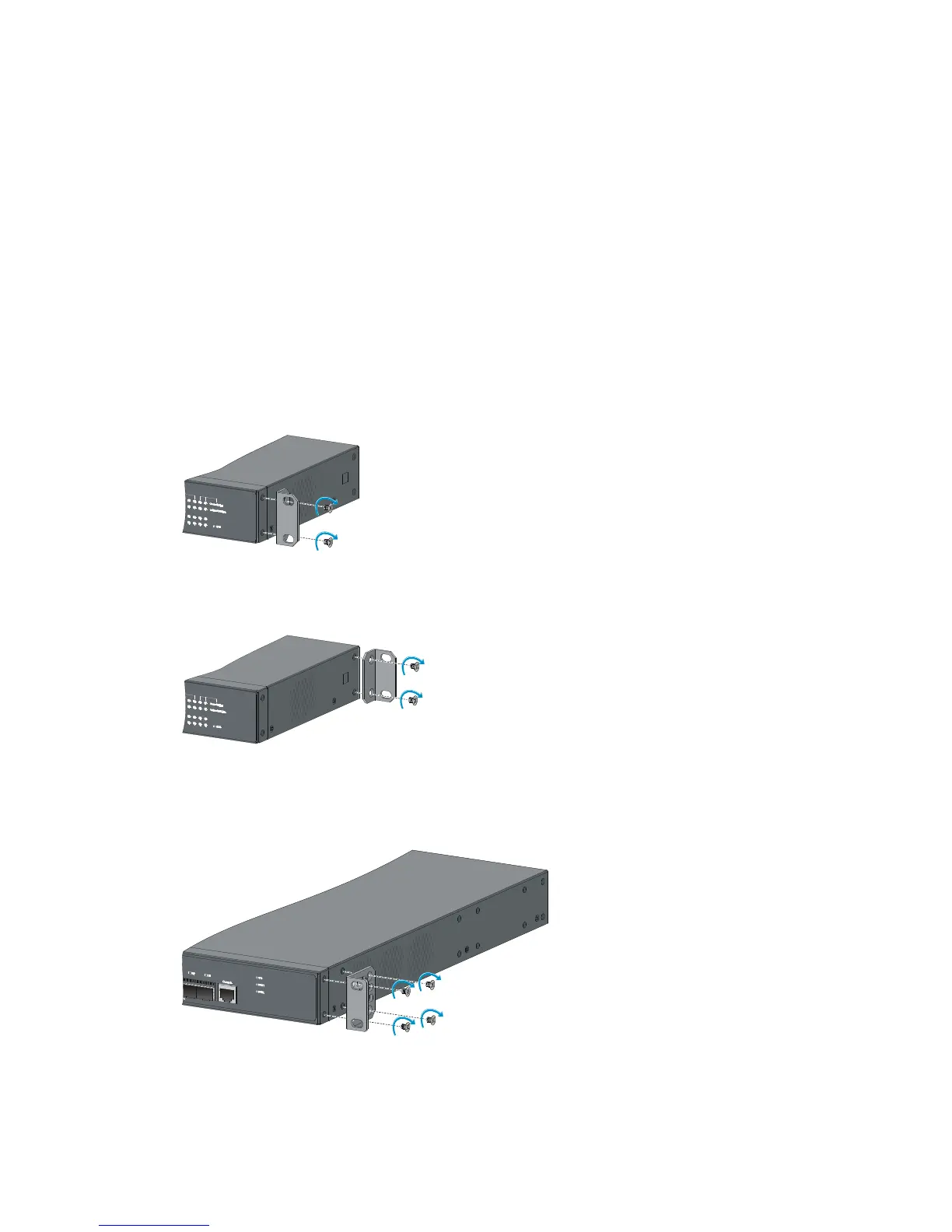
To attach the mounting brackets to the switch:
1. Determine the mounting position.
2. Align one mounting bracket with the screw holes at the mounting position. Use M4 screws
provided with the switch to attach the mounting bracket to the chassis.
3. Repeat step 2 to attach the other mounting bracket to the chassis.
Figure 4 Attaching a two-hole mounting bracket to the front mounting position on an HP
5130-24G-4SFP+ EI switch
Figure 5 Attaching a two-hole mounting bracket to the rear mounting position on an HP
5130-24G-4SFP+ EI switch
Figure 6 Attaching a four-hole mounting bracket to the front mounting position on an HP
5130-24G-SFP-4SFP+ EI switch
 Loading...


