EasyManua.ls Logo

HP 5400zl Series User Manual

HP 5400zl Series
128 pages
To Next Page IconTo Next Page
To Previous Page IconTo Previous Page
Page #104 background imageLoading...
Page #104 background image
B-8
Switch Ports and Network Cables
Twisted-Pair Cable/Connector Pin-Outs
Switch Ports and Network
Cables
Straight-Through Twisted-Pair Cable for
10 Mbps or 100 Mbps Network Connections
Because of the HP Auto-MDIX operation of the 10/100 ports on the switches,
for all network connections, to PCs, servers or other end nodes, or to hubs or
other switches, you can use straight-through cables.
If any of these ports are given a fixed configuration, for example 100 Mbps/
Full Duplex, the ports operate as MDI-X ports, and straight-through cables
must be then used for connections to PC NICs and other MDI ports.
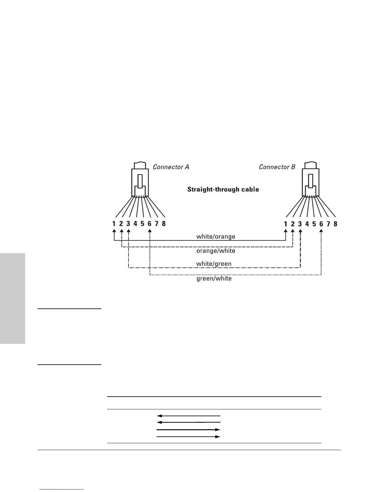
Cable Diagram
Figure B-2. Straight-through Cable Diagram for 10/100 Mbps Network Connection
Note Pins 1 and 2 on connector “A” must be wired as a twisted pair to pins 1 and 2
on connector “B”.
Pins 3 and 6 on connector “A” must be wired as a twisted pair to pins 3 and 6
on connector “B”.
Pins 4, 5, 7, and 8 are not used in this application, although they may be wired
in the cable.
.
Pin Assignments
Switch End (MDI-X) Computer, Transceiver, or Other End
Signal Pins Pins Signal
receive +
receive -
transmit +
transmit -
1
2
3
6
1
2
3
6
transmit +
transmit -
receive +
receive -

Table of Contents

Other manuals for HP 5400zl Series

Questions and Answers:

HP 5400zl Series Specifications

General IconGeneral
BrandHP
Model5400zl Series
CategorySwitch
LanguageEnglish

Summary

Introducing the ProCurve Series 5400zl Switches

Switch Chassis LEDs

Explains the status and meaning of various LEDs on the switch chassis for diagnostics.

Power Connectors and Supplies

Covers the AC power connector and redundant power supply options for switch operation.

Installing the Series 5400zl Switches

Installation Procedures

Provides a step-by-step overview of the entire installation process, from site prep to final connections.

Installation Precautions

Essential warnings and safety guidelines to follow before and during switch installation.

Install Switch Modules

Step-by-step instructions for inserting switch modules into the chassis slots.

Verify the Switch Passes Self Test

How to confirm the switch is operational by checking LEDs after self-test.

Connect the Network Devices

How to connect network cables to switch ports for establishing network connectivity.

(Optional) Connect a Console to the Switch

Instructions for connecting a console for initial switch configuration and management.

Replacing Components

Replacing Power Supplies

Step-by-step guide on how to remove and install AC power supplies.

Replacing the Management Module

Detailed instructions for removing and installing the management module.

Troubleshooting ProCurve Series 5400zl Switches

Basic Troubleshooting Tips

General advice and common issues to check first when troubleshooting network problems.

Diagnosing Issues with LEDs

Interpreting LED patterns on the switch and modules to identify problems and their causes.

Hardware Diagnostic Tests and Resetting

Performing hardware tests and understanding reasons/methods for resetting the switch.

Restoring Factory Default Configuration

Steps to reset the switch to its original factory default settings to resolve configuration issues.

Safety and Regulatory Statements

General Safety Information

General safety guidelines, grounding, and servicing information.

Related product manuals