EasyManua.ls Logo

HP 5400zl Series User Manual

HP 5400zl Series
128 pages
To Next Page IconTo Next Page
To Previous Page IconTo Previous Page
Page #49 background imageLoading...
Page #49 background image
2-23
Installing the Series 5400zl Switches
Installation Procedures
Installing the Series 5400zl
Switches
Operating Characteristics of the EPS (J8714A)
The Power Supply Shelf has two EPS Ports. The EPS can provide a maximum
of up to 900 watts of PoE power to each of the two EPS ports depending on
which power supply is used. It is important to understand the PoE power
requirements of the 5400zl Series switches because if the PoE power is not
planned and implemented correctly the end devices connected to the switch
ports may not receive power if an internal switch PoE power supply should
fail. For further information regarding the Power Supply Shelf PoE
capabilities, see the PoE (ProCurve Power over Ethernet) Devices Planning
and Implementation Guide and the ProCurve Power Supply Shelf
Installation and Getting Started Guide, which is on the ProCurve Web site.
See page 5-1 for details.
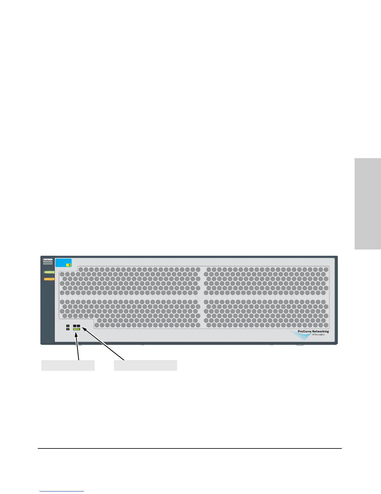
Power Supply Shelf LEDs
The EPS LEDs are duplicated on the front and back of the device. The
following graphic shows an example of the front of the EPS. There are two
dual colored (green/orange) LEDs for each EPS port:
Device Connected
Power Status
Power
Supply
Status
EPS Port
Status
E1 E2
ProCurve Switch zl
Power Supply Shelf
J8714A
Power
Fault
Device Connected
Power Status
PoE
Fault
Power
Device Connected LEDsPower Status LEDs

Table of Contents

Other manuals for HP 5400zl Series

Questions and Answers:

HP 5400zl Series Specifications

General IconGeneral
BrandHP
Model5400zl Series
CategorySwitch
LanguageEnglish

Summary

Introducing the ProCurve Series 5400zl Switches

Switch Chassis LEDs

Explains the status and meaning of various LEDs on the switch chassis for diagnostics.

Power Connectors and Supplies

Covers the AC power connector and redundant power supply options for switch operation.

Installing the Series 5400zl Switches

Installation Procedures

Provides a step-by-step overview of the entire installation process, from site prep to final connections.

Installation Precautions

Essential warnings and safety guidelines to follow before and during switch installation.

Install Switch Modules

Step-by-step instructions for inserting switch modules into the chassis slots.

Verify the Switch Passes Self Test

How to confirm the switch is operational by checking LEDs after self-test.

Connect the Network Devices

How to connect network cables to switch ports for establishing network connectivity.

(Optional) Connect a Console to the Switch

Instructions for connecting a console for initial switch configuration and management.

Replacing Components

Replacing Power Supplies

Step-by-step guide on how to remove and install AC power supplies.

Replacing the Management Module

Detailed instructions for removing and installing the management module.

Troubleshooting ProCurve Series 5400zl Switches

Basic Troubleshooting Tips

General advice and common issues to check first when troubleshooting network problems.

Diagnosing Issues with LEDs

Interpreting LED patterns on the switch and modules to identify problems and their causes.

Hardware Diagnostic Tests and Resetting

Performing hardware tests and understanding reasons/methods for resetting the switch.

Restoring Factory Default Configuration

Steps to reset the switch to its original factory default settings to resolve configuration issues.

Safety and Regulatory Statements

General Safety Information

General safety guidelines, grounding, and servicing information.

Related product manuals