2-3
Installing the Series 5400zl Switches
Installation Procedures
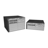
Installing the Series 5400zl
Switches
Installation Procedures
Summary
Follow these easy steps to install your switch. The rest of this chapter provides
details on these steps.
1. Prepare the installation site (page 2-7). Make sure the physical
environment into which you will be installing the switch is properly
prepared including having the correct network cabling ready to connect
to the switch, and having a good location for the switch. See page 2-6 for
some installation precautions.
2. Install switch modules (page 2-9). The Series 5400zl Switches have six
or 12 universal slots for installing any of the ProCurve Switch zl modules.
The Switch 5406zl-48G has two 24-port 10/1001000-T zl Modules
preinstalled and the 5412zl-96G has four 24-port 10/1001000-T zl Modules
preinstalled. Depending on where you will install your Series 5400zl
Switch, it may be easier to install the modules first. The modules are “hot
swappable” though, so they can also be installed and removed after the
switch is powered on.
Note Make sure you use only ProCurve Switch zl Modules in your Series 5400zl
Switches.
3. Install power supplies (page 2-12). The Series 5406zl Switches supports
up to two power supplies. It may be easier to install the power supplies
before mounting the switch. The switch must have at least one power
supply to operate.
4. Verify the switch passes self test (page 2-15). This is a simple process
of plugging the switch into a power source and observing that the LEDs
on the switch’s front panel and on the modules show correct operation.
It may be easier to verify if the switch passes self test before mounting
the switch.
5. Mount the switch (page 2-17). The Series 5400zl Switches can be
mounted in a 19-inch telco rack, in an equipment cabinet, or on a
horizontal surface. An optional Rail Mounting Kit (5070-0145) is available
for mounting Series 5400zl Switches in a cabinet suitable for shipping. See
the installation details for more information.
6. Install the Grounding Wire (page 2-21). If a grounding wire is to be
attached to the switch chassis, the grounding lug must be removed and a
wire crimped to it and the grounding lug must be reinstalled.