Performance Tests
Power Reference Level Test
HP EPM-441A/442A Service Guide 2-11
Equipment
Test power meter ................................... HP 432A
Thermistor Mount ................................ HP 478A Option H75 or H76
Digital Voltmeter (DVM)....................... HP 3458A
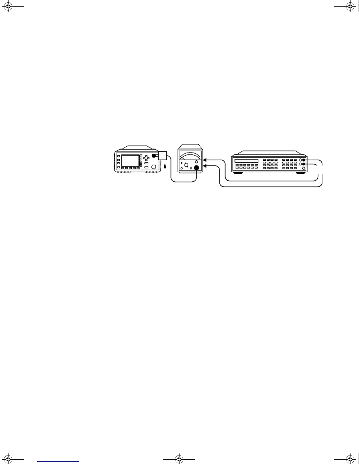
Test Setup
Figure 2-3: Power Reference Level Test Setup
Procedure
The following equation allows the Power Reference Oscillator power to be
calculated by measuring the voltages V
0
, V
1
, V
comp
, and the resistance R.
The definitions of the terms in this equation are:
•V
0
is the voltage measured between V
comp
and V
RF
with no power
applied and after the HP 432A has been zeroed.
•V
1
is the voltage measured between V
comp
and V
RF
with power
applied. This power is approximately 1 mW.
•V
comp
is the voltage between the HP 432A V
comp
connector and
chassis ground with power applied.
• R is the resistance of the mount resistor in the HP 432A power
meter.
• Calibration Factor is the value of the thermistor mount at
50 MHz.
Power Meter
V
RF
Vcomp
HP 478A
Option H75
Digital
Multimeter
POWER
REF
INPUT
+
HP 432A
Power Meter
INPUT
P
meas
2V
comp
V
1
V
0
–()V
0
2
V
1
2
–+
4R CalibrationFactor
()
-----------------------------------------------------------------------------------=
4402serv.book Page 11 Monday, March 11, 2002 11:34 AM
 Loading...