Replaceable Parts
Assembly and Disassembly Guidelines
HP EPM-441A/442A Service Guide 5-9
Removing the A2 Processor Assembly
1. Remove the A5 daughter and A6 measurement assemblies as
described on page 5-11.
2. Move the A2 plastic support bracket to its forward position using
the two side levers, then disconnect the front panel keypad and
front panel LCD cables from the A2 assembly.
3. Disconnect the following cables from the A2 processor assembly:
■ power reference semi-rigid
■ fan connector
■ power supply connector
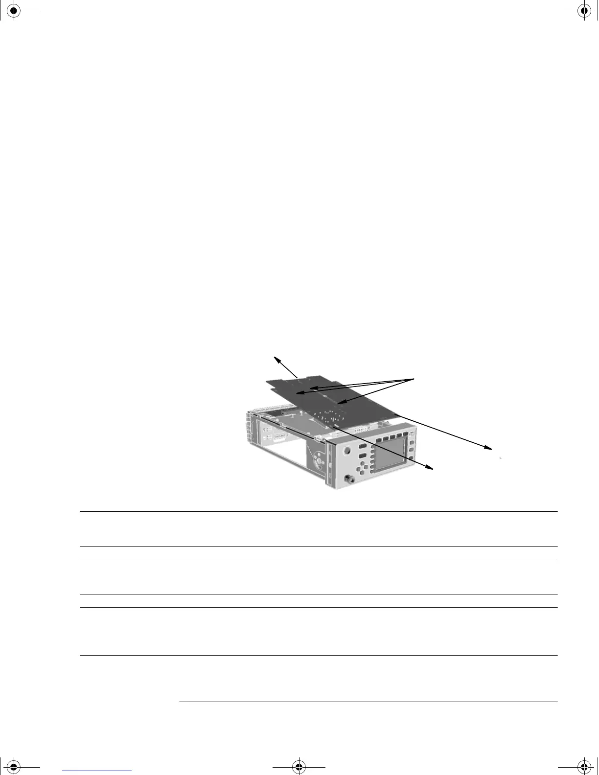
4. Turn the power meter upside down and remove the three screws
as shown. (When replacing these screws use a 6 lb/in T10 screw
driver.)
5. Push the A2 processor assembly towards the front panel to release
it from the 50-pin connector. Lift it upwards to remove.
Note When re-assembling the processor board, ensure the A2 plastic
support bracket is returned to its locked position.
Note After replacing a processor board, the display brightness and
contrast must be adjusted. See Chapter 3 “Adjustments”.
Note Firmware should be downloaded to the instrument after the
processor board is replaced. Refer to “Downloading Firmware”, on
page 5-6.
screws
4402serv.book Page 9 Monday, March 11, 2002 11:34 AM
 Loading...