128
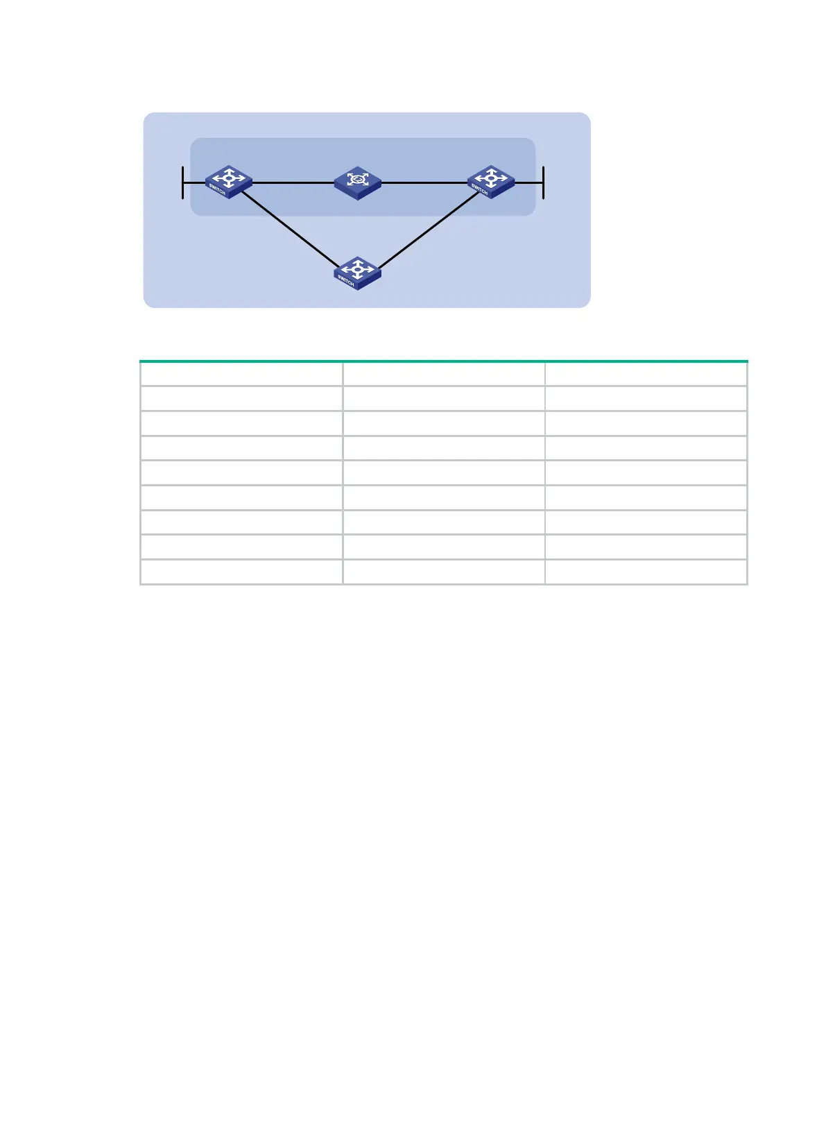
Figure 33 Network diagram
Table 9 Interface and IP address assignment
Switch A Vlan-int10 192.168.0.102/24
Switch A Vlan-int11 10.1.1.102/24
Switch A Loop0 121.1.1.1/32
Switch B Vlan-int10 192.168.0.100/24
Switch B Vlan-int13 13.1.1.1/24
Switch B Loop0 120.1.1.1/32
Switch C Vlan-int11 10.1.1.100/24
Switch C Vlan-int13 13.1.1.2/24
Configuration procedure
1. Configure IP addresses for interfaces. (Details not shown.)
2. Enable OSPF:
# Configure Switch A.
<SwitchA> system-view
[SwitchA] ospf
[SwitchA-ospf-1] area 0
[SwitchA-ospf-1-area-0.0.0.0] network 192.168.0.0 0.0.0.255
[SwitchA-ospf-1-area-0.0.0.0] network 10.1.1.0 0.0.0.255
[SwitchA-ospf-1-area-0.0.0.0] network 121.1.1.1 0.0.0.0
[SwitchA-ospf-1-area-0.0.0.0] quit
[SwitchA-ospf-1] quit
# Configure Switch B.
<SwitchB> system-view
[SwitchB] ospf
[SwitchB-ospf-1] area 0
[SwitchB-ospf-1-area-0.0.0.0] network 192.168.0.0 0.0.0.255
[SwitchB-ospf-1-area-0.0.0.0] network 13.1.1.0 0.0.0.255
[SwitchB-ospf-1-area-0.0.0.0] network 120.1.1.1 0.0.0.0
[SwitchB-ospf-1-area-0.0.0.0] quit
[SwitchB-ospf-1] quit
Switch A Switch B
Vlan-int10
Vlan-int10
BFD
L2 Switch
Area 0
Switch C
Vlan-int11
Vlan-int11
Vlan-int13
Vlan-int13
Loop0
Loop0
 Loading...


