468
[SwitchS] interface vlan-interface 100
[SwitchS-Vlan-interface100] ospfv3 1 area 1
[SwitchS-Vlan-interface100] quit
[SwitchS] interface vlan-interface 200
[SwitchS-Vlan-interface200] ospfv3 1 area 1
[SwitchS-Vlan-interface200] quit
Verifying the configuration
# Verify the following:
When an active/standby switchover occurs on Switch S, the neighbor relationships and routing
information on Switch A and Switch B have not changed. (Details not shown.)
The traffic from Switch A to Switch B has not been impacted. (Details not shown.)
BFD for OSPFv3 configuration example
Network requirements
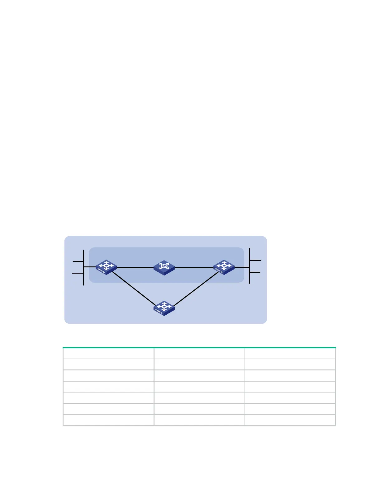
As shown in Figure 108:
Configure OSPFv3 on Switch A, Switch B and Switch C and configure BFD over the link Switch
A<—>L2 Switch<—>Switch B.
After the link Switch A<—>L2 Switch<—>Switch B fails, BFD can quickly detect the failure and
notify OSPFv3 of the failure. Then Switch A and Switch B communicate through Switch C.
Figure 108 Network diagram
Table 26 Interface and IP address assignment
Switch A Vlan-int10 2001::1/64
Switch A Vlan-int11 2001:2::1/64
Switch B Vlan-int10 2001::2/64
Switch B Vlan-int13 2001:3::2/64
Switch C Vlan-int11 2001:2::2/64
Switch C Vlan-int13 2001:3::1/64
Configuration procedure
1. Configure IPv6 addresses for the interfaces. (Details not shown.)
2. Configure basic OSPFv3:
Switch A
Switch B
Vlan
-int10
Vlan
-int10
BFD
L2 Switch
Area 0
Switch C
Vlan-
int11
Vlan-
int11
Vlan
-int1
3
Vlan-int
13
2001
:4::/
64
2001:
1
::/64
 Loading...


