 Loading...
Do you have a question about the HP HPE SimpliVity 380 Gen10 and is the answer not in the manual?
| Processor | Intel Xeon Scalable processors |
|---|---|
| Hypervisor Support | VMware vSphere, Microsoft Hyper-V |
| Network | 10GbE |
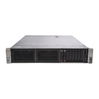
| Form Factor | 2U |
| Power Supply | Redundant Power Supplies |
| Operating System | Windows Server |
| Management | HPE OneView |
| Memory | Up to 6 TB DDR4 ECC Registered DIMMs |
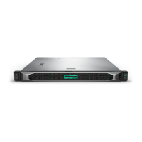
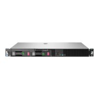
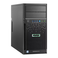
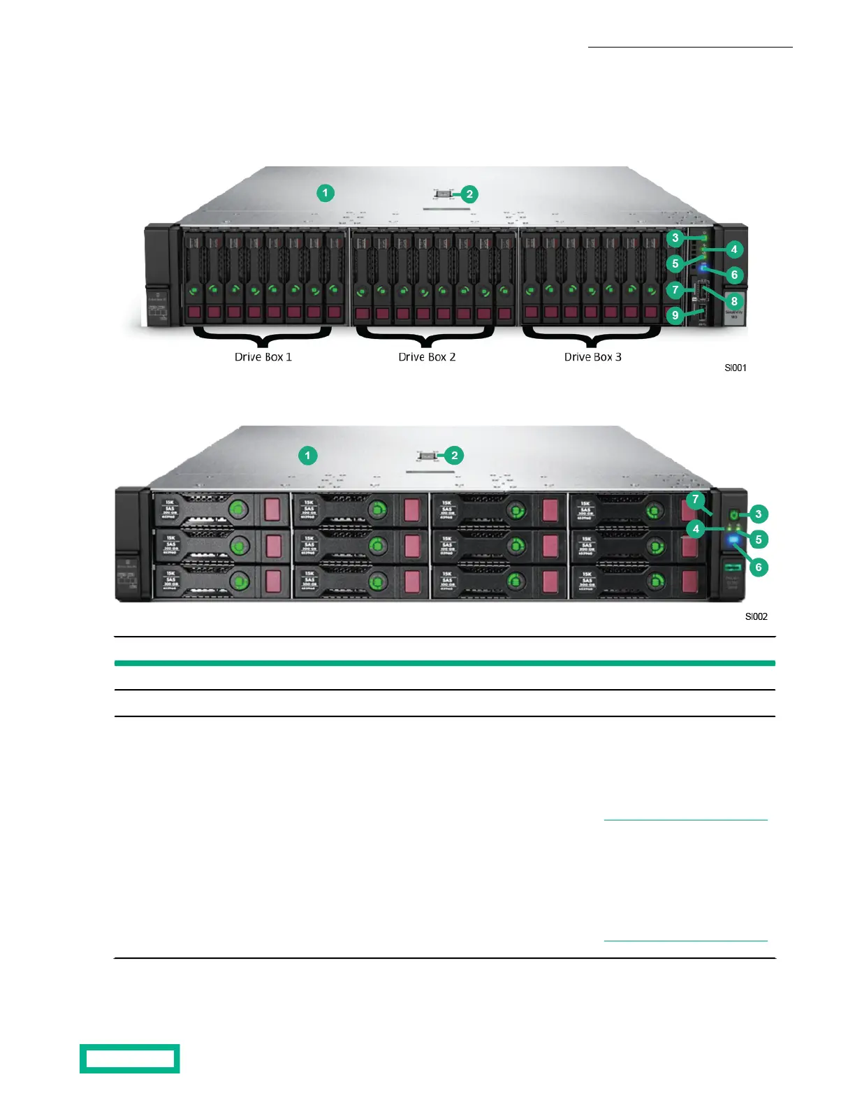
Details various HPE SimpliVity 380 server models and their configurations.
Describes the controls, indicators, and ports on the server's front panel.
Details the ports, power supplies, and boot drives on the server's back panel.
Step-by-step instructions for mounting the server into its rack rails.
Steps to configure the iLO port for out-of-band web-based management.
Instructions for accessing the server remotely via the Integrated Remote Console.
Explains front panel LEDs that indicate server status and hardware errors.
Instructions for safely removing a failed or failing SSD from the server.
Steps for installing a replacement SSD or filler panel into a drive slot.
Steps to safely remove a failed or failing power supply from the server.