Before removing the RGB board, follow these steps:
1. Prepare the computer for disassembly (Preparation for disassembly on page 31).
2. Remove the bottom cover (Bottom cover on page 31).
3. Remove the solid-state drive to the left of the battery (Solid-state drive on page 32).
4. Remove the battery (see Battery on page 37).
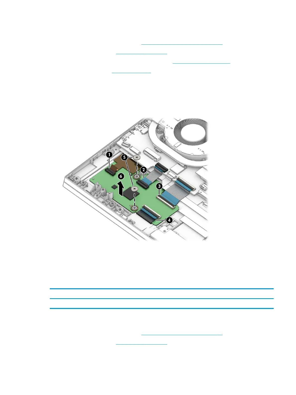
Remove the RGB board:
1. Disconnect the four cables from the ZIF connectors on the RGB board (1)–(4).
2. Remove the two Phillips M2.0 × 4.0 screws (5) that secure the board to the computer.
3. Remove the RGB board from the computer (6).
Reverse this procedure to install the RGB keyboard control board.
Power connector cable
To remove the power connector cable, use this procedure and illustration.
Table
6-3 Power connector cable description and part number
Description Spare part number
Power connector cable L98734-001
Before removing the power connector cable, follow these steps:
1. Prepare the computer for disassembly (Preparation for disassembly on page 31).
2. Remove the bottom cover (Bottom cover on page 31).
Component replacement procedures 39
 Loading...