WLAN module
Description
Intel Dual Band Wireless-AC 7265 NV
Intel Dual Band Wireless-AC 8265 (vPro)
Intel Dual Band Wireless-AC 8265 (non-vPro)
Intel Dual Band Wireless-AC 3168
802.11bgn, 1x1, single band, Bluetooth 4.1 combo module
The WLAN module is located near the top of the system board. The WLAN module is secured with one Phillips
screw and has two connected antennas.
NOTE: The procedure to replace the WLAN module must be performed by an HP technician.
To remove the WLAN module:
1. Prepare the computer for disassembly (see Preparing to disassemble the computer on page 19).
2. Remove the rear port cover (see Rear port cover on page 23).
3. Remove the stand (see Attaching and removing a stand on page 20).
4. Remove the access panel (see Access panel on page 24).
5. Remove the system board shield (see System board (EMI) shield on page 30).
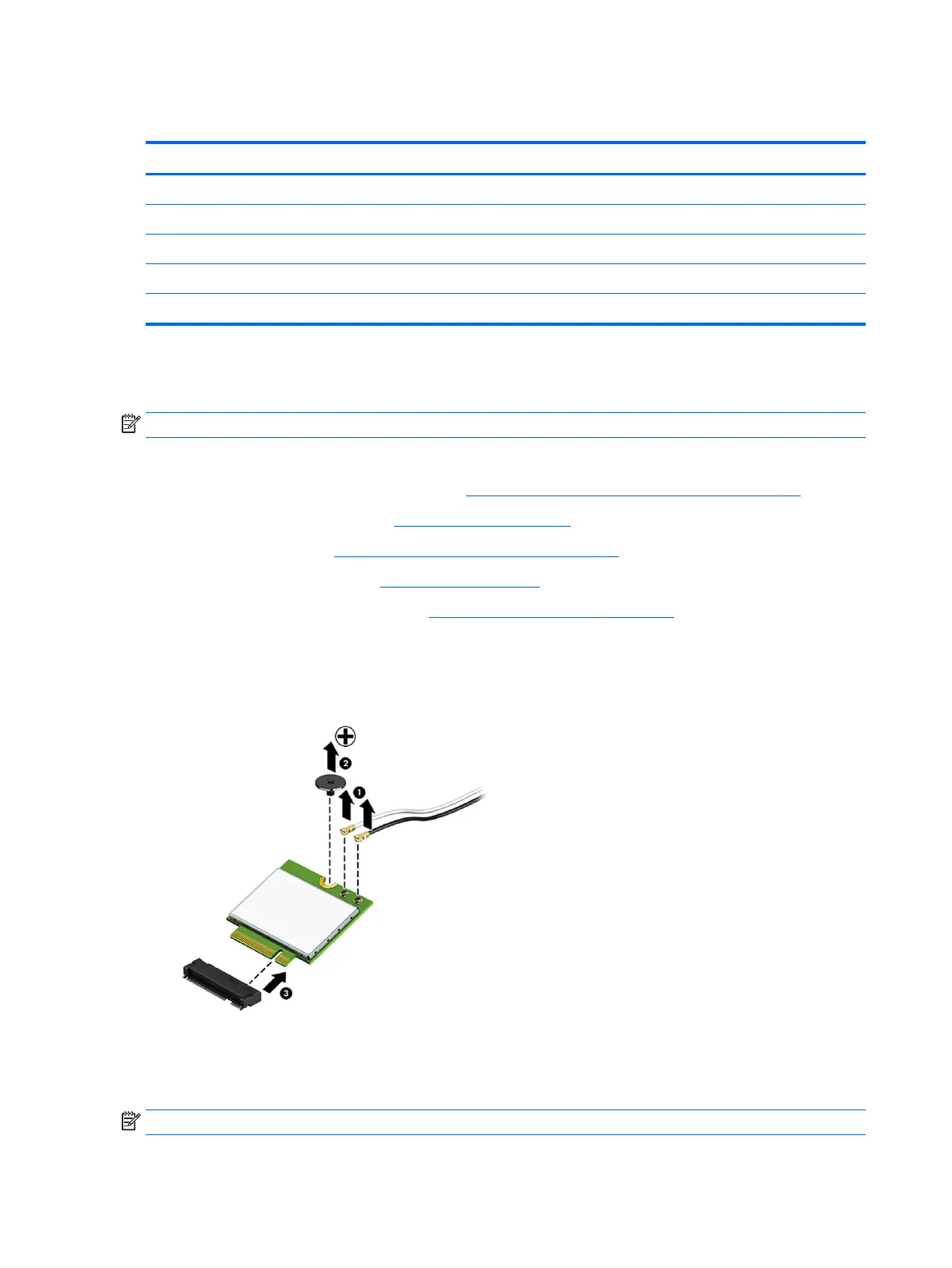
6. Disconnect the antenna cables from the module (1).
7. Remove the Phillips screw (2) that secures the module to the computer.
8. Lift the module to a 45-degree angle, and then pull it away to remove it from the socket (3).
To install the WLAN module, reverse the removal procedures.
When connecting the antennas cables, connect the cable labeled “1” (black sticker) to the AUX “1” connector
on the module and the cable labeled “2” (white sticker) to the MAIN “2” connector on the module.
NOTE: WLAN modules are designed with a notch to prevent incorrect insertion.
34 Chapter 4 Removal and Replacement Procedures
 Loading...