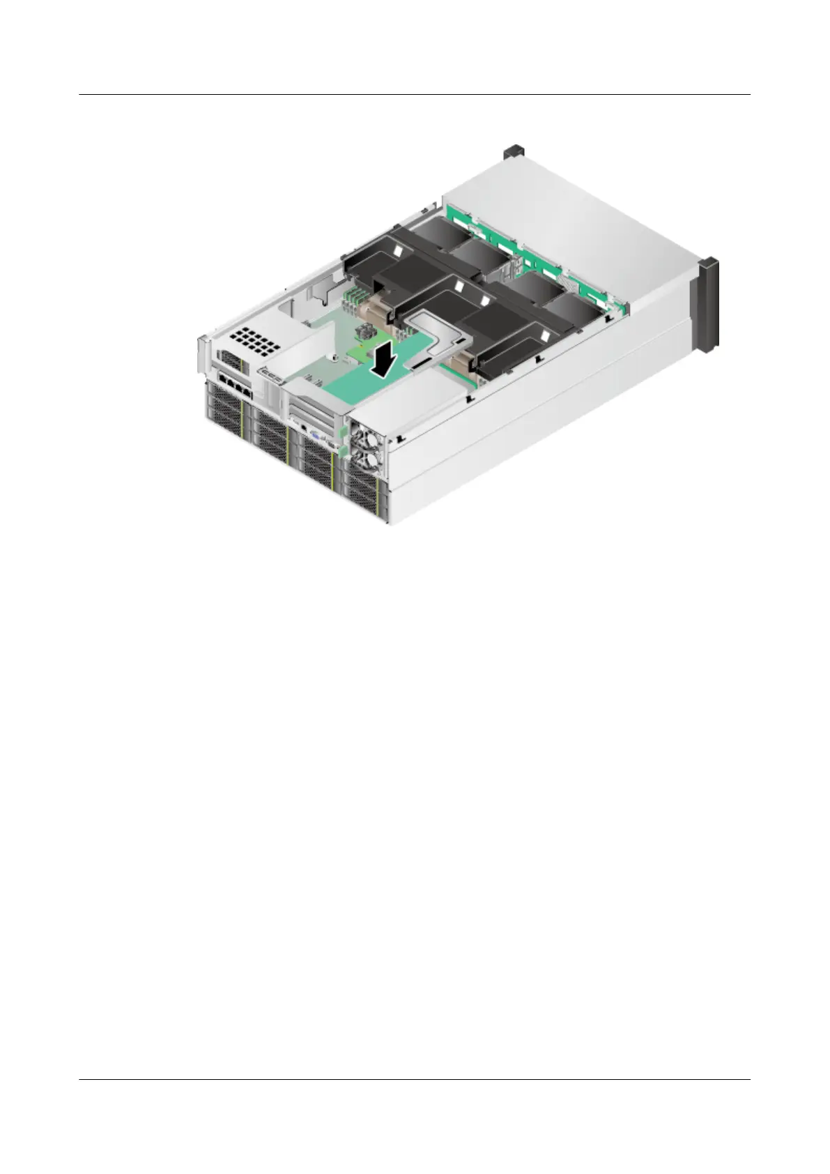
Figure 7-48 Installing a riser card tray
Step 7 Connect cables to the riser card.
Step 8 Install the chassis cover. For details, see 7.12 Installing the Chassis Cover.
Step 9 Install the 5288 V3. For details, see 3.4 Installing the Server.
Step 10 Connect all internal cables such as power and network cables. For details, see 3.5 Connecting
External Cables.
Step 11 Power on the 5288 V3. For details, see 4.1 Powering On the Server.
----End
7.22.2 Installing a PCIe Card on the Mainboard
Install a non-hot-swappable PCIe card to replace the original one.
Procedure
Step 1 Wear an ESD wrist strap. For details, see 1 Safety Instructions.
Step 2 Remove from the mainboard the PCIe card to be replaced. For details, see 7.21.2 Removing a
PCIe Card from the Mainboard.
Step 3 Take the spare PCIe card out of its ESD bag.
Step 4 Insert the PCIe card into a PCIe slot. See step (1) in Figure 7-49.
5288 V3 Server
User Guide
7 Replacing Parts
Issue 26 (2018-11-19) Copyright © Huawei Technologies Co., Ltd. 162
 Loading...