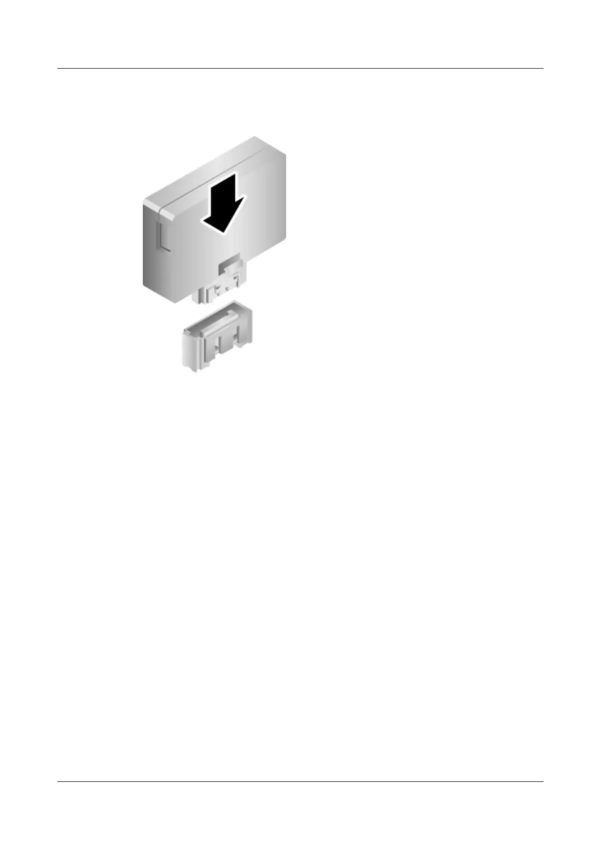
Step 5 Insert the SATADOM vertically into the connector on the mainboard. See Figure 7-97.
Figure 7-97 Installing a SATADOM
Step 6 Install the chassis cover. For details, see 7.12 Installing the Chassis Cover.
Step 7 Install the 5288 V3. For details, see 3.4 Installing the Server.
Step 8 Connect all internal cables such as power and network cables. For details, see 3.5 Connecting
External Cables.
Step 9 Power on the 5288 V3. For details, see 4.1 Powering On the Server.
----End
Verification
1. Start the server. When the BIOS startup screen is displayed, press Delete to start the
BIOS Setup Utility.
2. Enter a BIOS password when prompted.
3. Choose Advanced > PCH SATA Configuration and press Enter.
Check the component information to verify whether the replacement is successful.
SATADOM 1 and SATADOM 2 correspond to Serial ATA Port 4 and Serial ATA Port
5 respectively.
7.47 Removing an SD Card
Remove a Secure Digital (SD) card before replacing it with a new one.
5288 V3 Server
User Guide
7 Replacing Parts
Issue 26 (2018-11-19) Copyright © Huawei Technologies Co., Ltd. 213
 Loading...