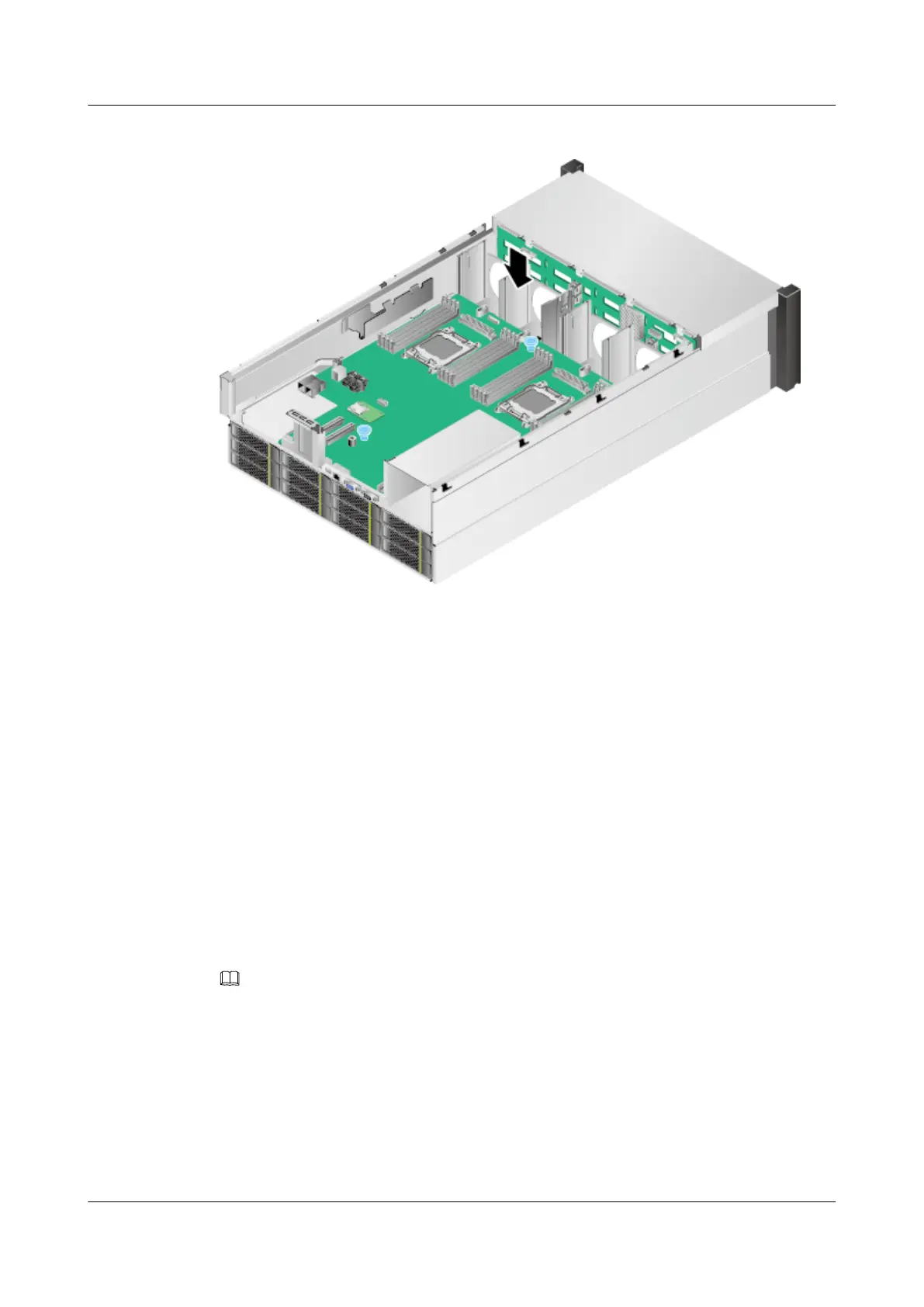
Figure 7-90 Installing fan module brackets
Step 16 Install the fan modules. For details, see 7.16 Installing a Fan Module.
Step 17 Install the air duct. For details, see 7.14 Installing the Air Duct.
Step 18 Install the riser cards. For details, see 7.20 Installing a Riser Card.
Step 19 Install the supercapacitor if it is required. For details, see 7.35 Installing the Supercapacitor
(RAID Controller Card).
Step 20 Install the chassis cover. For details, see 7.12 Installing the Chassis Cover.
Step 21 Install the 5288 V3. For details, see 3.4 Installing the Server.
Step 22 Connect all internal cables such as power and network cables. For details, see 3.5 Connecting
External Cables.
Step 23 Power on the 5288 V3. For details, see 4.1 Powering On the Server.
Step 24 (Optional) To burn the original equipment serial number (ESN) into the new mainboard after
replacement, contact Huawei engineers.
NOTE
If original device SN is not burnt in the new mainboard, the iBMC and OS cannot obtain the device SN.
This may affect the running of some services or the monitoring and management on the device.
Step 25 (Optional) Configure the server.
l If the iBMC and BIOS configuration data is exported before the mainboard replacement,
import the data to the server and configure the password. For details, see Import/Export
in the Huawei Server Firmware Upgrade Guide.
l To upgrade the firmware (iBMC, BIOS, and CPLD) of the mainboard after replacement,
see the Huawei Rack Server iBMC User Guide.
5288 V3 Server
User Guide
7 Replacing Parts
Issue 26 (2018-11-19) Copyright © Huawei Technologies Co., Ltd. 206
 Loading...