INSTALLATION
HPR130 Manual Gas Instruction Manual 3-37
5
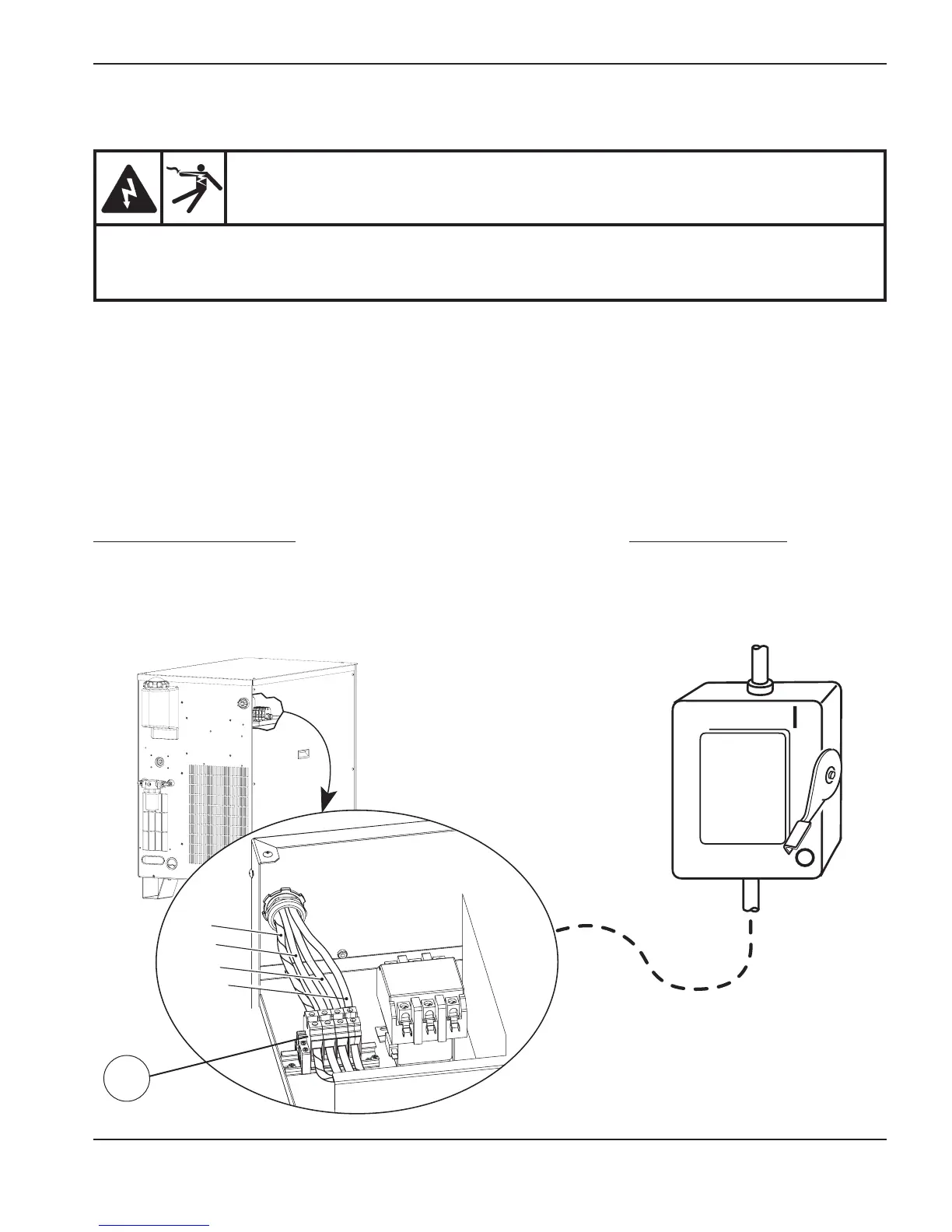
Connect the power
1. Insert the power cable through the strain relief at the rear of the power supply.
2. Connect the ground lead (PE) to the GND terminal of TB1 as shown below.
3. Connect the power leads to the terminals of TB1 as shown below.
4. Check that the line disconnect switch is in the OFF position and remains in the OFF position for the
remainder of the installation of the system.
5. Connect the power cord leads to the line disconnect switch following national or local electrical codes.
DANGER
ELECTRICAL SHOCK CAN KILL
The line disconnect switch must be in the OFF position before making the power cable connections.
In the U.S., use a “lock-out/tag-out” procedure until installation is complete. In other countries,
follow appropriate national or local safety procedures.
Line
disconnect
switch
Power
cable
TB1
W
V
GND
U
North American wire colors
U = Black
V = White
W = Red
(PE) Earth ground = Green/Yellow
European wire colors
U = Black
V = Blue
W = Brown
(PE) Earth ground = Green/Yellow

 Loading...


