46 MAXPRO200 Instruction Manual 807700 Revision 1
Installation
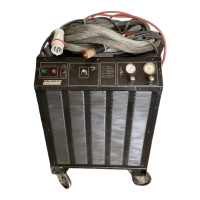
The following picture shows an example of a cutting table ground bus. The components shown here may differ from your
system.
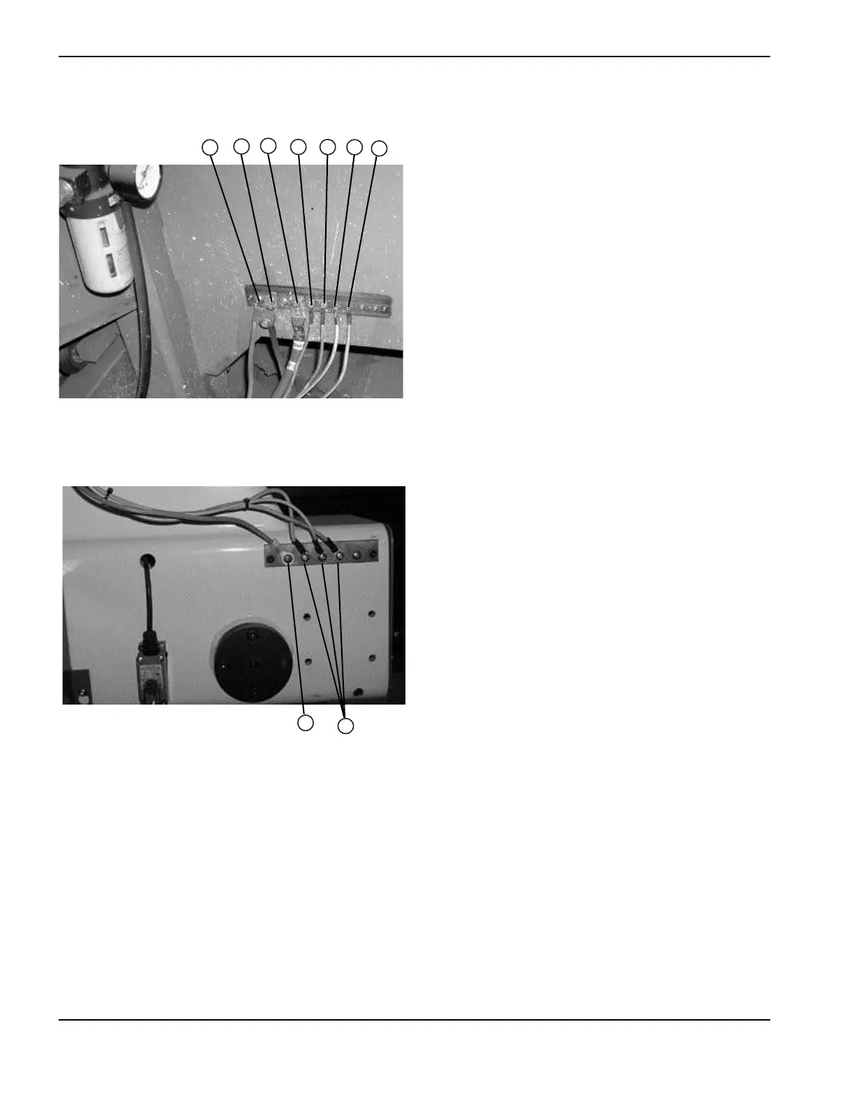
The following picture shows an example of a gantry ground bus. It is bolted to the gantry, close to the motor. All of the
individual ground cables from the components mounted on the gantry go to the bus. A single heavy cable then goes from
the gantry ground bus to the table ground bus,
The following diagram shows an example of grounding the components in a plasma cutting system.
1 Gantry ground bus
2 Ground rod
3 Plasma system lead (+)
4 Remote high frequency (RHF) console
5 CNC enclosure
6 Torch holder
7 Plasma system chassis
1
1 Cable to the cutting table ground bus
2 Ground cables from components on the gantry

 Loading...