SETUP
powermax1650 Operator Manual 3-15
2
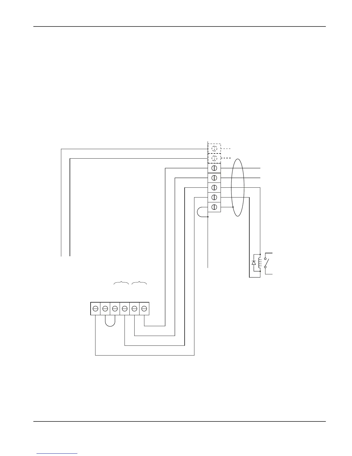
Changing XFER (start machine motion) from dry contact closure to
voltage signal
24 VDC (chassis ground reference) at 100ma max is available at J19 on the powerboard to drive
an isolated/floating device such as a 24 VDC relay coil (240 ohms or greater) or a typical industrial
isolated input module (which has an opto-coupler built-in). Shown below are typical connections
for a high-side drive arrangement.
Driving a relay coil
Notes:
1. Customer supplied 24 VDC
relay coil > 240 ohms.
2. Must use suppression diode
(1A, 100V) such as IN4002
through IN4004 type across
coil.
3. Pins 5 and 6 are used only on
systems that include the
PowermaxEDGE cable with
voltage divider.
Move the black (BLK) wire
to ground (GND) and add
a jumper wire as shown.
5
V-div –
6
V-div +
4
3
14
12
13
Shield
J16
J15
J19
GND
24VDC
BLK
YEL
RED
WHT
XFER START
Start
Signal
BLK

 Loading...