OPERATION
3
4-16 powermax1650 Operator Manual
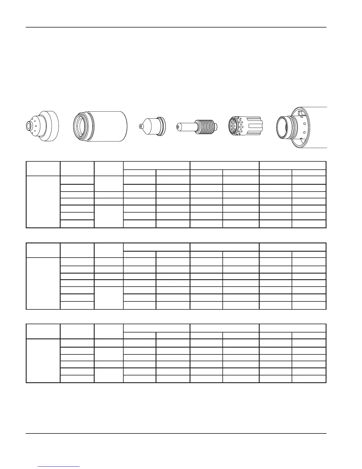
60 amp mechanized shielded consumables
• Torch-to-work dis tance for the following cut chart is 1/16 in (1.5 mm) for all cuts.
Retaining cap
120928
Nozzle
120931
Electrode
120926
Swirl ring
120925
T100M-2
torch
Shield
120930
Maximum travel speeds are the fastest speeds possible for cutting the material without regard to cut quality. Optimum travel
speeds provide the best cut angle, least dross and best cut surface finish. Remember that cut charts are intended to
provide a good starting point for each different cut assignment. Every cutting system requires “fine tuning” for each
cutting application in order to obtain the desired cut quality.
Arc current Arc voltage
Pierce
delay
Material thickness
Maximum travel speed Optimum travel speed
Inches mm
IPM mm/min IPM mm/min
60
134
0
16 Ga 1.5
627 15926 502 12751
134
10 Ga 3.4
264 6706 211 5359
138 0.25
1/4” 6.4
132 3353 86 2184
141 0.75
3/8” 9.5
63 1600 41 1041
141
1.50
1/2” 12.7
42 1067 27 686
147
5/8” 15.9
31 787 20 512
153
3/4” 19.0
22 559 14 363
Arc current Arc voltage
Pierce
delay
Material thickness
Maximum travel speed Optimum travel speed
Inches mm
IPM mm/min IPM mm/min
60
135 0
1/16” 1.6
666 16916 433 10995
138
0.25
1/8” 3.2
400 10160 260 6604
141
1/4” 6.4
145 3683 94 2388
146 0.75
3/8” 9.5
74 1880 48 1219
149
1.50
1/2” 12.7
51 1295 30 762
153
5/8” 15.9
33 838 21 545
Mild steel
Stainless steel
Aluminum
Arc current Arc voltage
Pierce
delay
Material thickness
Maximum travel speed Optimum travel speed
Inches mm
IPM mm/min IPM mm/min
60
134 0
16 Ga 1.5
625 15875 406 10312
136 0.25
10 Ga 3.4
244 6198 159 4039
139 0.50
1/4” 6.4
110 2794 72 1829
145 0.75
3/8” 9.5
53 1346 34 864
146
2.00
1/2” 12.7
35 889 23 584
149
5/8” 15.9
26 660 17 429
154
3/4” 19.0
18 457 12 297

 Loading...