OPERATION
3
powermax1650 Operator Manual 4-17
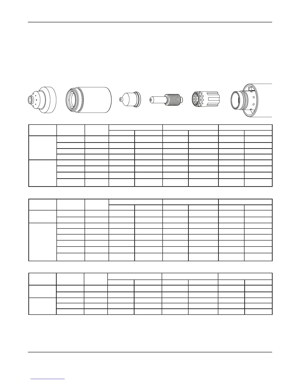
40 amp mechanized shielded consumables
• Torch-to-work dis tance for the following cut chart is 1/16 in (1.5 mm) for all cuts.
Retaining cap
120928
Nozzle
120932
Electrode
120926
Swirl ring
120925
T100M-2
torch
Shield
120930
Maximum travel speeds are the fastest speeds possible for cutting the material without regard to cut quality. Optimum travel
speeds provide the best cut angle, least dross and best cut surface finish. Remember that cut charts are intended to
provide a good starting point for each different cut assignment. Every cutting system requires “fine tuning” for each
cutting application in order to obtain the desired cut quality.
Arc current Arc voltage
Pierce
delay
Material thickness
Maximum travel speed Optimum travel speed
Inches mm
IPM mm/min IPM mm/min
25
147
26 GA 0.5
638 16205 415 10541
148
22 GA 0.8
500 12700 325 8255
149
18 GA 1.3
312 7925 203 5156
152
16 GA 1.5
176 4470 114 2896
40
144 0.25
14 GA 1.9
640 16256 221 5613
146 0.50
10 GA 3.4
151 3835 98 2489
147 0.75
3/16” 4.7
97 2464 63 1600
149 1.00
1/4” 6.4
74 1880 48 1219
Arc current Arc voltage
Pierce
delay
Material thickness
Maximum travel speed Optimum travel speed
Inches mm
IPM mm/min IPM mm/min
25
150
1/32” 0.8
610 15494 397 10084
152
1/16” 1.5
268 6807 174 4420
40
146 0.25
3/32” 2.4
293 7442 190 4826
149 0.50
1/8” 3.2
204 5182 133 3378
151 1.00
1/4” 6.4
76 1930 49 1245
Mild steel
Stainless steel
Aluminum
Arc current Arc voltage
Pierce
delay
Material thickness
Maximum travel speed Optimum travel speed
Inches mm
IPM mm/min IPM mm/min
25
139
26 GA 0.5
631 16027 410 10414
139
22 GA 0.8
496 12598 322 8179
40
142 0.25
18 GA 1.3
592 15037 335 8509
144 0.25
16 GA 1.5
374 9500 243 6172
144 0.25
14 GA 1.9
221 5613 144 3658
147 0.50
10 GA 3.4
107 2718 70 1778
149 0.75
3/16” 4.7
67 1702 44 1118
149 1.00
1/4” 6.4
47 1194 31 787

 Loading...