Powermax30 XP Service Manual 808150 Revision 0 131
6 – Power Supply Component Replacement
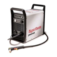
3. Push-to-disconnect the gas supply hose from the fitting on the rear-panel side of the solenoid valve. (See Figure 56
on page 119.)
4. Push-to-disconnect the gas supply hose from the fitting on the front-panel side of the solenoid valve.
Figure 64
5. Remove the 2 screws that attach the solenoid valve’s bracket to the center panel.
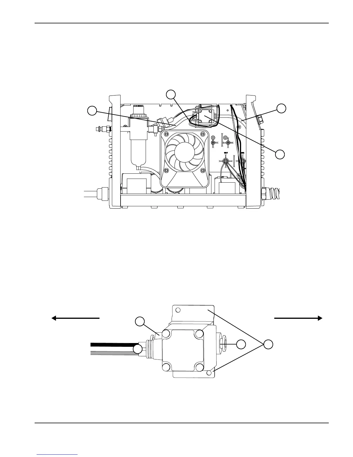
6. Orient the new solenoid valve so that the pink-and-gray J6 wire pair is on the rear-panel side of the valve.
Figure 65
1
Gas supply hose (rear-panel side)
2
Solenoid valve
3
Gas supply hose (front-panel side)
4
J6 wire pair
1
3
2
1
(Rear panel)
(Front panel)
1
Push-to-connect fitting
2
Pink-and-gray J6 wire pair
3
Solenoid valve bracket

 Loading...