138 Powermax30 XP Service Manual 808150 Revision 0
6 – Power Supply Component Replacement
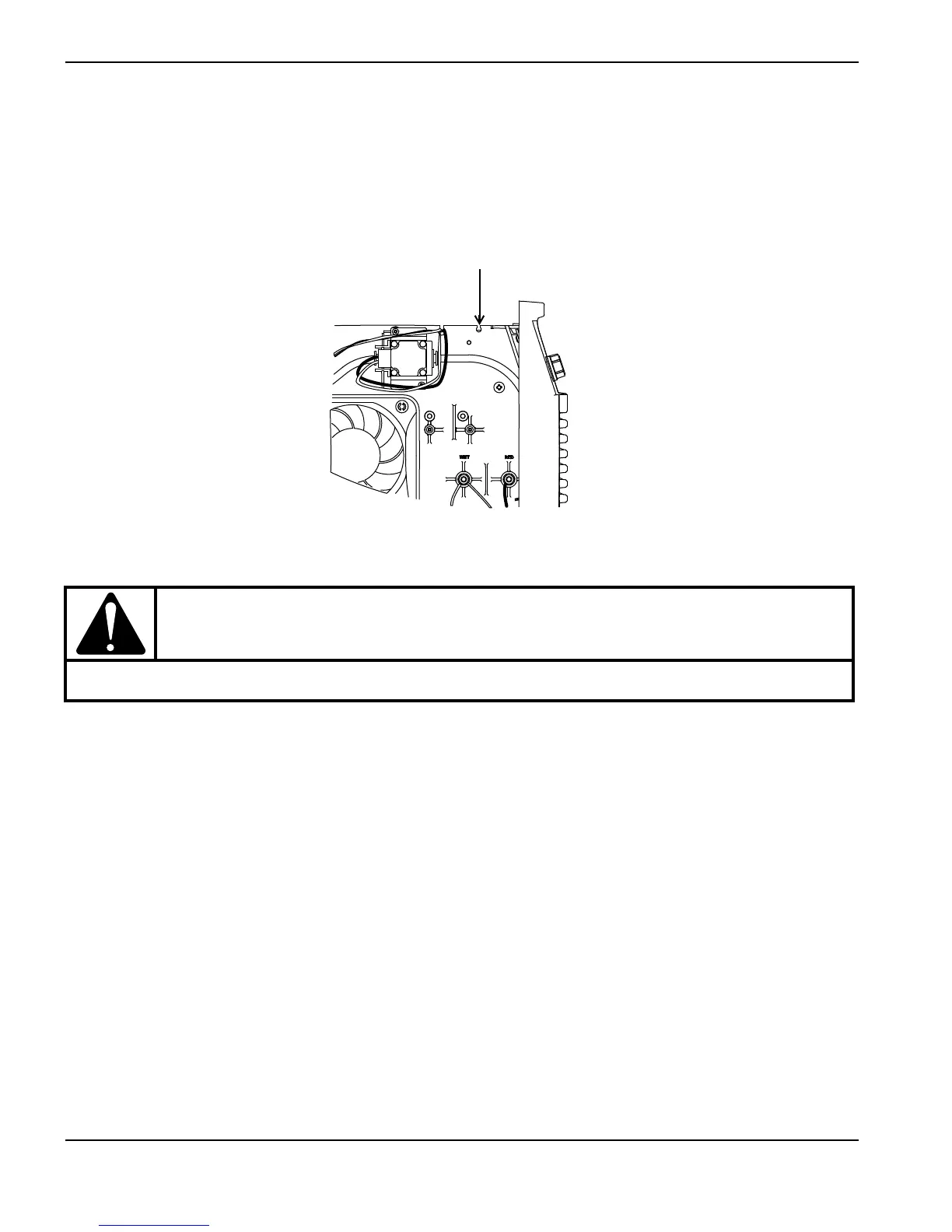
7. Route the orange, blue, and purple wire group over the center panel, with the wires resting in the notch in the panel
that is closest to the front of the power supply. (See Figure 73 on page 138.)
8. Press the connector into the TORCH START slot (J12) on the power board. (See Figure 69 on page 135.)
Figure 73
9. From the inside of the front panel, tighten the retention nut onto the strain relief.
10. Tighten the torch lead’s strain relief nut onto the strain relief as you put the front panel back in place. See Reattach
the front panel on page 94.
11. Complete the following procedures:
a. See Install the power supply cover on page 89.
b. Reconnect the gas supply and power cord, and set the power switch to ON (I).
CAUTION!
Be careful not to twist the torch lead as you tighten the retention nut onto the strain relief.
Route the torch lead’s orange, blue, and purple wires through this notch in the center panel

 Loading...