Powermax30 XP Service Manual 808150 Revision 0 83
5 – Troubleshooting and System Tests
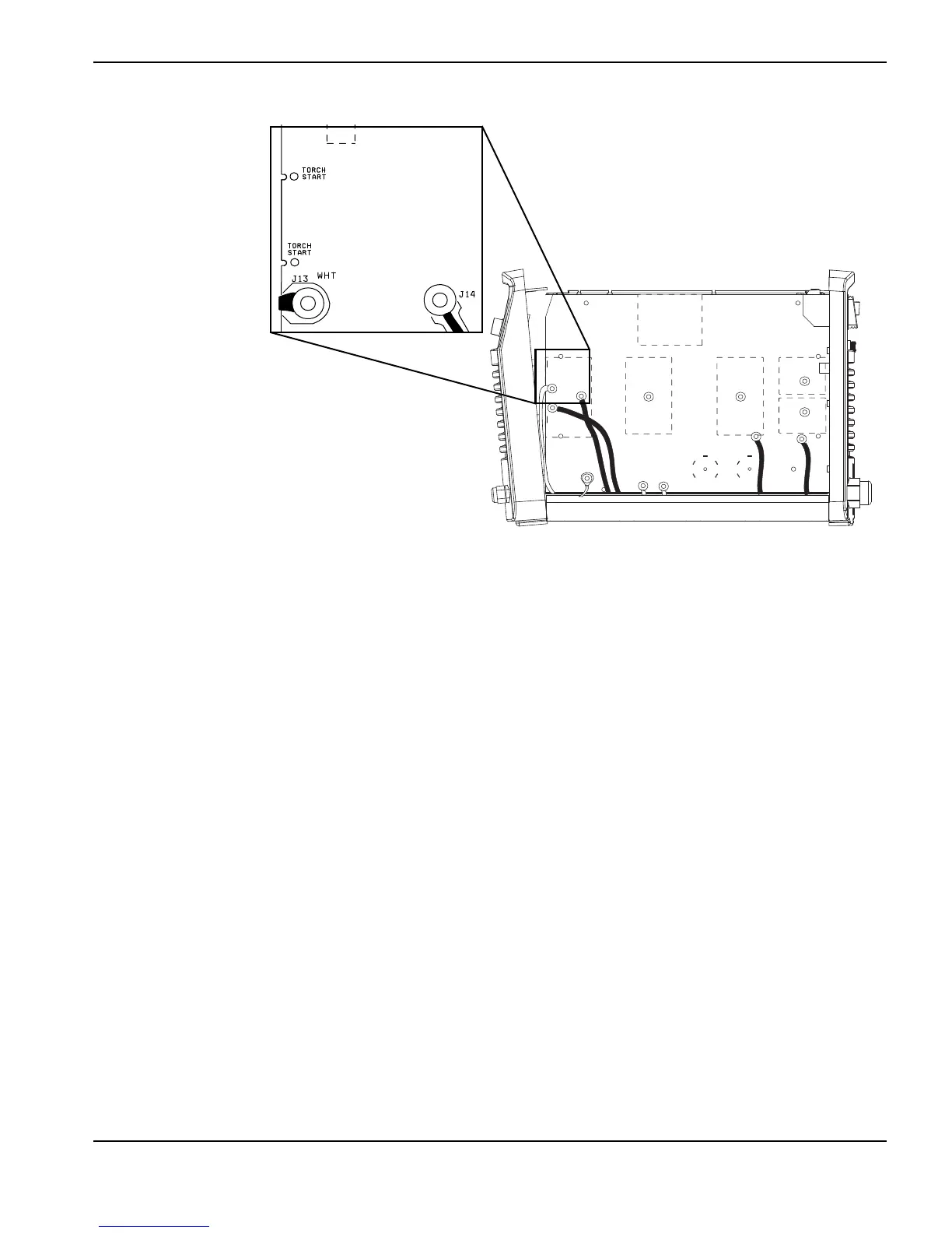
Figure 21
9. Turn ON (I) the power.
10. Measure pin 16 of J7 to ground. (See Test 2 – power board voltage checks on page 76.)
a. With the trigger pulled, it should measure as 0 VDC for an open circuit.
b. With the trigger released, it should measure 3.2 VDC for a closed circuit.
11. If the values are not correct, replace the power board. (See Remove the power board on page 109.)

 Loading...