3-2
MAINTENANCE
powermax600 Service Manual
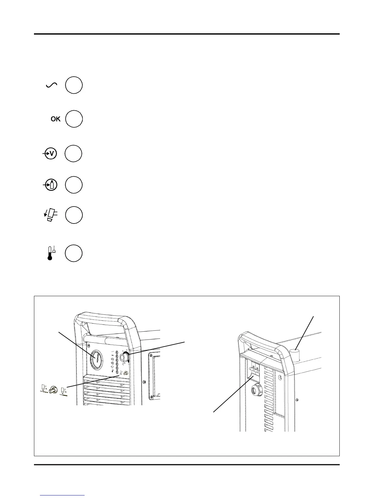
Pressure
Gauge
Current
Adjustment
Knob
Pressure
Regulator
ON (I)/OFF (0)
Switch
Figure 3-1 Powermax600 Controls
Controls - See Figure 3-1.
Green POWER IS ON
When illuminated, indicates that AC voltage is supplied to the power supply
and that the ON/OFF switch is in the ON position.
Green SYSTEM READY
When illuminated, indicates that circuits are activated and that all fault
conditions are clear (none of the yellow lamps are illuminated).
Yellow LOW LINE VOLTAGE
When illuminated, indicates that the AC line voltage is: 1) below operating
limits ,or 2) is missing 1 phase (230V and 400V systems only).
Yellow LOW GAS PRESSURE
When illuminated, indicates that the incoming gas pressure is below operat-
ing limits.
Yellow TORCH PARTS ARE LOOSE OR REMOVED
When illuminated, indicates that the torch consumables are loose or not
installed.
Yellow HIGH TEMPERATURE
When illuminated, indicates that the power supply temperature has ex-
ceeded operating limits.
CONTROLS AND INDICATORS
Indicator Lamps
Pilot Arc
Control Switch
(208-240, 480V)
11-99

 Loading...