MAINTENANCE
3-31
powermax600 Service Manual
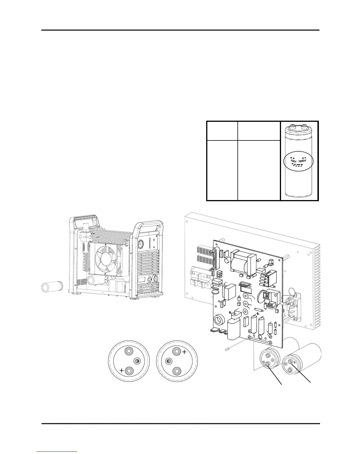
Installation - Refer to Figure 3-15.
Check capacitor identification and install as
shown below.
Install new capacitor and secure with 2 screws.
Tighten screws to 20 inch pounds (2.26 N-m /
24 kg cm).
Install the power supply cover.
+ Positive
+ Positive
Capacitor Replacement
Figure 3-15 Capacitor Replacement
Remove and install
capacitors from fan side.
Power Capacitor
Supply Marking
208/240V 250V 6800uf
230V 250V 4700uf
400V 400V 1800uf
480V 450V 1500uf
Capacitor Identification
Removal - Refer to Figure 3-15.
Disconnect electrical power and gas supply before removing the power supply cover.
Remove screws securing capacitor to PC board.
Remove capacitor from fan side of power supply.
11-99

 Loading...