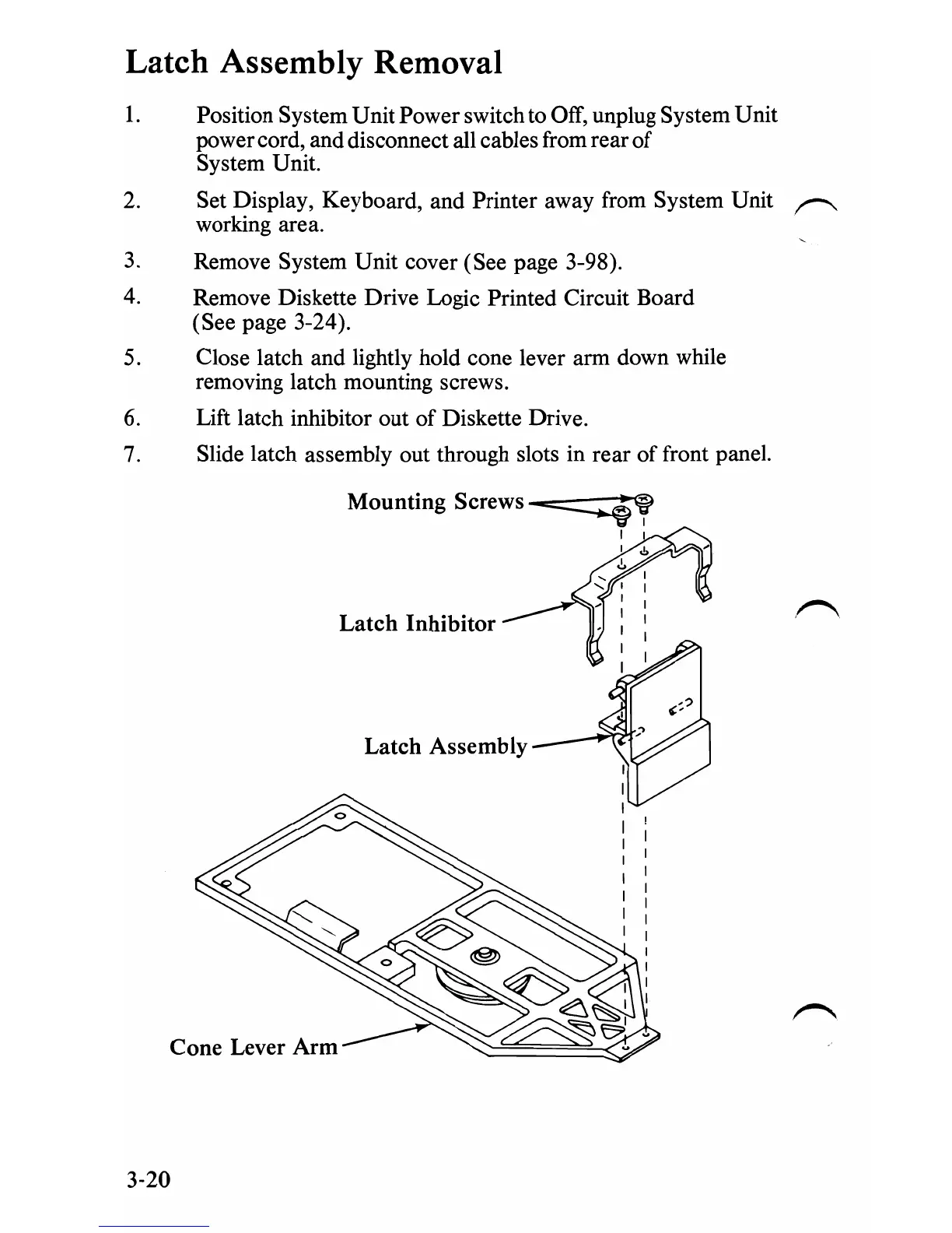
Latch Assembly Removal
1.
Position System Unit Power switch to Off, unplug System Unit
power cord, and disconnect all cables from rear
of
System Unit.
2.
Set Display, Keyboard, and Printer away from System Unit
~
working area.
3.
Remove System Unit cover (See page 3-98).
4.
Remove Diskette Drive Logic Printed Circuit Board
(See page 3-24).
5.
Close latch and lightly hold cone lever arm down while
removing latch mounting screws.
6. Lift latch inhibitor out
of
Diskette Drive.
7.
Slide latch assembly out through slots in rear
of
front panel.
Mounting Screws
-=::::::::;:::f'
I I
I .!,
.!,
Latch
Inhibitor
Latch
Assembly
3-20
 Loading...