Latch Assembly Replacement
1.
2.
r--.., 3.
4.
5.
6.
7.
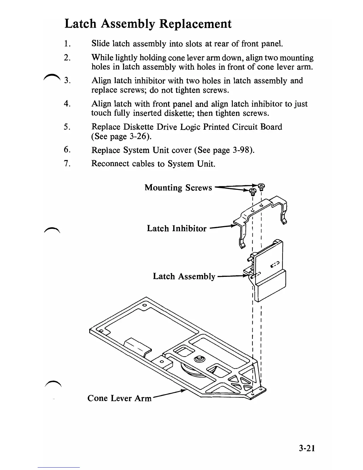
Slide latch assembly into slots
at
rear
of
front panel.
While lightly holding cone lever arm down, align two mounting
holes in latch assembly with holes in front
of
cone lever arm.
Align latch inhibitor with two holes in latch assembly and
replace screws; do not tighten screws.
Align latch with front panel and align latch inhibitor to just
touch fully inserted diskette; then tighten screws.
Replace Diskette Drive Logic Printed Circuit Board
(See page 3-26).
Replace System Unit cover (See page 3-98).
Reconnect cables to System Unit.
Mounting
Screws
-=:::--:~
Latch
Inhibitor
Latch
Assembly
__
~:)If
3-21
 Loading...