Monitoring the Device
● Interpreting port-side LEDs............................................................................................. 67
● Interpreting nonport-side LEDs....................................................................................... 70
● Interpreting the POST results..........................................................................................71
● Interpreting the BOOT results......................................................................................... 72
● Running diagnostic tests................................................................................................. 72
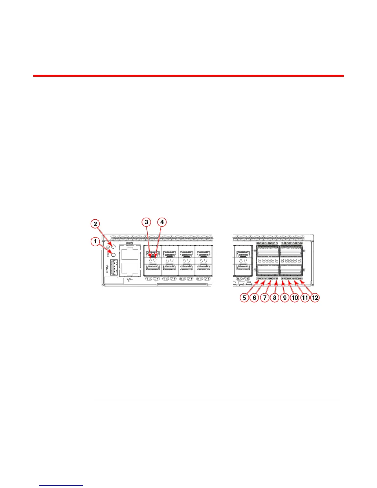
Interpreting port-side LEDs
System activity and status can be determined through the activity of the LEDs on the switch. There are
three possible LED states: no light, a steady light, and a flashing light. Flashing lights may be slow, fast,
or flickering. The lights are green or amber. Sometimes, the LEDs flash either of the colors during boot,
POST, or other diagnostic tests. This is normal; it does not indicate a problem unless the LEDs do not
indicate a healthy state after all boot processes and diagnostic tests are complete.
1 System status LED
2 System power LED
3 SFP+ (upper) port 0 status LED
4 SFP+ (lower) port 4 status LED
5 FC port 52 (QSFP 1) status LED
6 FC port 53 (QSFP 1) status LED
7 FC port 54 (QSFP 1) status LED
8 FC port 55 (QSFP 1) status LED
9 FC port 60 (QSFP 3) status LED
10 FC port 61 (QSFP 3) status LED
11 FC port 62 (QSFP 3) status LED
12 FC port 63 (QSFP 3) status LED
FIGURE 29 Port-side LEDs
NOTE
The two LEDs on the serial console port are non-functional.
System power LED
Refer to the following table to interpret the system power status LED.
Hardware Installation Guide 67
 Loading...