Identifying the airflow direction
CAUTION
Use a separate branch circuit for each power cord, which provides redundancy in case one of
the circuits fails.
CAUTION
To prevent damage to the chassis and components, never attempt to lift the chassis using the
fan or power supply handles. These handles were not designed to support the weight of the
chassis.
Identifying the airflow direction
The power supply and fan assemblies are identified by the following airflow directions:
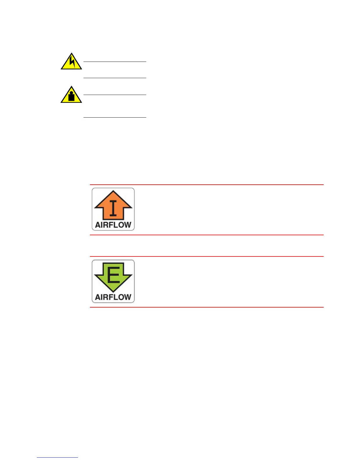
• Intake power supply and fan assembly with an orange "I" label or without any label: Pulls air
from the nonport-side of the switch and exhausts it out the port side.
• Nonport-side air intake
• Port-side air exhaust
• Back-to-front (nonport-side to port-side) airflow
• Part numbers ending with -R
• Exhaust power supply and fan assembly with a green "E" label: Pulls air from the port side of the
switch and exhausts it out the nonport-side.
• Nonport-side air exhaust
• Port-side air intake
• Front-to-back (port-side to nonport-side) airflow
• Part numbers ending with -F
Power supply and fan assembly status LED
Refer to the following table to interpret the power supply and fan assembly status LED during normal
operation.
Hardware Installation Guide 77
 Loading...