Note: The cable is routed on the outside of the chassis and connected to the
system board. The cable must be protected by the cable cover on the side of
the chassis.
6. Install PCI riser-card assembly 2 (see “Replacing a PCI riser-card assembly” on
page 208).
7. Install the air baffle (see “Replacing the air baffle” on page 262).
8. Rotate the hot-swap rear hard disk drive cage down (see “Rotating the
hot-swap rear hard disk drive cage down” on page 169.
9. Install the server top cover (see “Replacing the server top cover” on page 260).
10. Reconnect the external cables; then, reconnect the power cords and turn on
the peripheral devices and the server.
Removing the front USB connector assembly
Use this information to remove the front USB connector assembly.
About this task
To remove the front USB connector assembly that is on the side of the server,
complete the following steps:
1. Read the safety information that begins on page “Safety” on page vii and
“Installation guidelines” on page 32.
2. Turn off the server (see “Turning off the server” on page 22) and all attached
peripheral devices. Disconnect all power cords; then, disconnect all external
cables as necessary to replace the device.
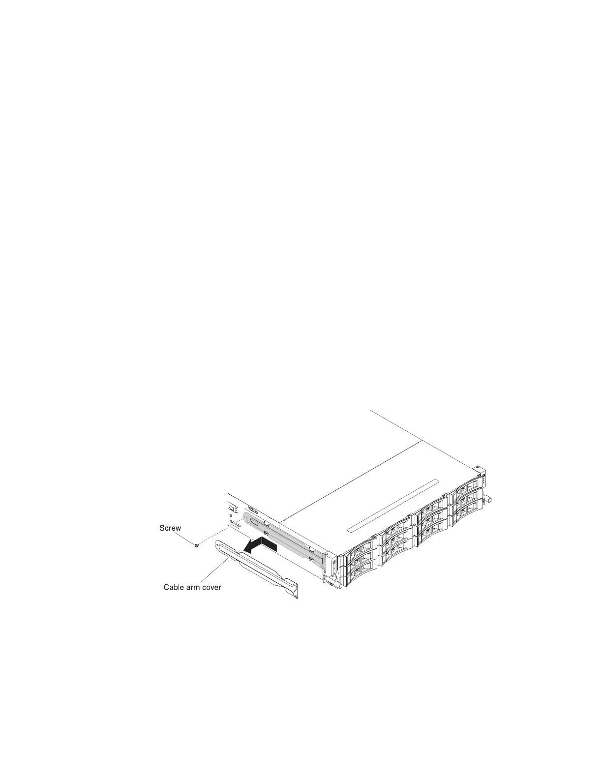
3. Remove the screws from the cable arm cover; then, slide the cable arm cover
towards the rear of the server and set it aside.
4. Remove the screws that secure the front USB connector assembly to the side of
the server.
5. Disconnect the cable to the front USB connector assembly.
Figure 129. Screw removal
218 System x3650 M4 BD Type 5466: Installation and Service Guide
 Loading...


