63
9
CONNECTIONS AND MAINTENANCE
9
r Return the cables and screws to the original position.
•Besurenotupsidedowntheatcable.
CAUTION:
•When re-assemblingthe case and tightening the
screws, you must keep the specified torque (0.5±0.07
N.m). Otherwise the transceiver may be damaged
(torque too high) or lose waterproof efficiency (torque
too low).
•Whenuninstallingtheoptionalunit,removeitvertically.
Wiggling the unit from side to side may damage the op-
tional unit's connector.
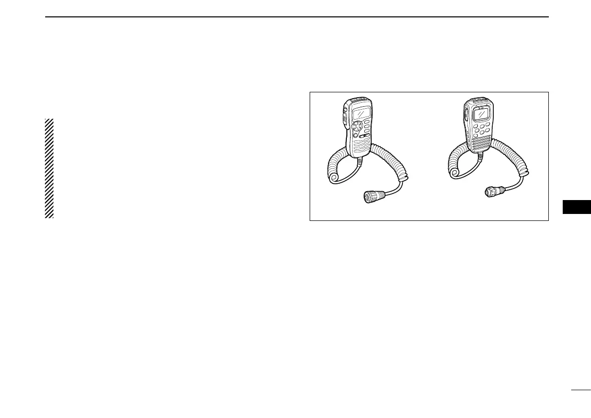
■ HM-162/HM-157 installation
The optional HM-157 can be connected to the transceiver di-
rectly, as well as via the supplied connection cable for longer
distance remote operation. The connector of the connection
cable can be installed into a cabinet, wall, etc., as a built-in plug.
•TheoptionalHM-162shouldbeinstalledtothetransceiverusing
the supplied connection cable.
For longer distance remote operation, the optional extension
cable, OPC-1541/OPC-999* (6 m; 20 ft/connecting between
transceiver and the connection cable), is available, and up to
two OPC-1541/OPC-999* can be added.
* OPC-1541 : For the HM-162
OPC-999 : For the HM-157
Do not connect the HM-162 to the OPC-999, and the HM-
157 to the OPC-1541.

 Loading...