100
1
7
4
10
15
18
2
8
13
5
11
16
3
9
14
6
12
17
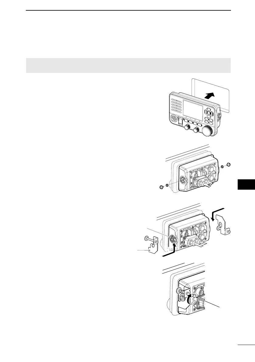
CONNECTIONS AND MAINTENANCE
12
1.
hole in the instrument panel, or wherever you plan
to mount the transceiver.
2. Slide the transceiver through the hole, as shown
on the right.
3. Attach the 2 bolts (5 × 8 mm) and spacer supplied
with the MBF-7 to both sides of the transceiver.
(Torque: 2 N•m)
Attach the clamps on both sides of the
transceiver.
L Make sure that the clamps align
parallel to the transceiver body.
5. Tighten the end bolts on the clamps (rotate
clockwise) so that the clamps press firmly against
the inside of the instrument control panel.
Clamp
End bolt
■ MBF-7 installation
The optional MBF-7
(less than 20 mm thick), such as an instrument panel.
NOTE: Install the transceiver and/or microphone more than 1 meter from the vessel’s
magnetic navigation compass.
Supplied bolt
4
4
5

 Loading...