101
12
CONNECTIONS AND MAINTENANCE
■ Microphone installation
When you use the supplied or optional HM-205RB , the optional
6 meters long OPC-1000 can be connected between the transceiver
and the HM-205RB to operate from even longer distances.
For the optional HM-195 and HM-229 , you can install the
connection cable’s connector on the wall in the same way.
L
NOTE:
them to the transceiver.
D Installation
1. Insert the connection cable connector into the command microphone jack, and
tighten the nut.
2. To use the cable connector as a wall socket, install it as shown below.
3. Using the mounting base as a template, carefully mark the holes where the cable
and 3 screws will be fastened.
Drill holes at these marks.
5. Install the mounting base using the supplied screws, as shown below.
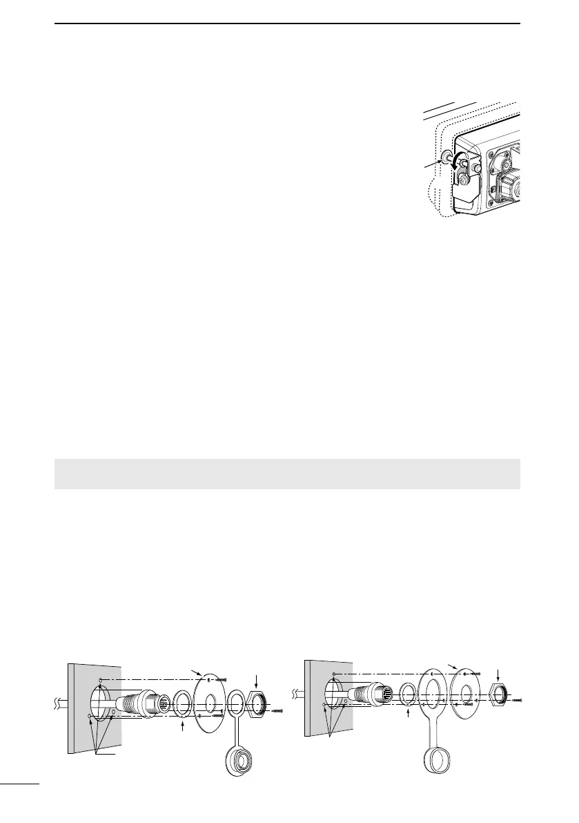
6. Tighten the locking nuts (rotate counterclockwise)
so that the transceiver is securely mounted in
position, as shown on the right. (Torque: 2 N•m)
7. Connect the antenna and power cable, and then
return the instrument control panel to its original
place.
6
Locking nut
■ MBF-7 installation
Mounting base
Nut
Gasket
Cap
Screw holes
2 (d) mm, 1/16 inch)
HM-205RB
Mounting base
Nut
Cap
Gasket
Screw holes
1/16 inch)
HM-195

 Loading...