27
CHAPTER 5
CHAPTER 5 - EXALT COMBI UNITS - DOMESTIC PIPING
5.1. Domestic Piping Pressure Relief Valve
5.1.1 Standard Installation
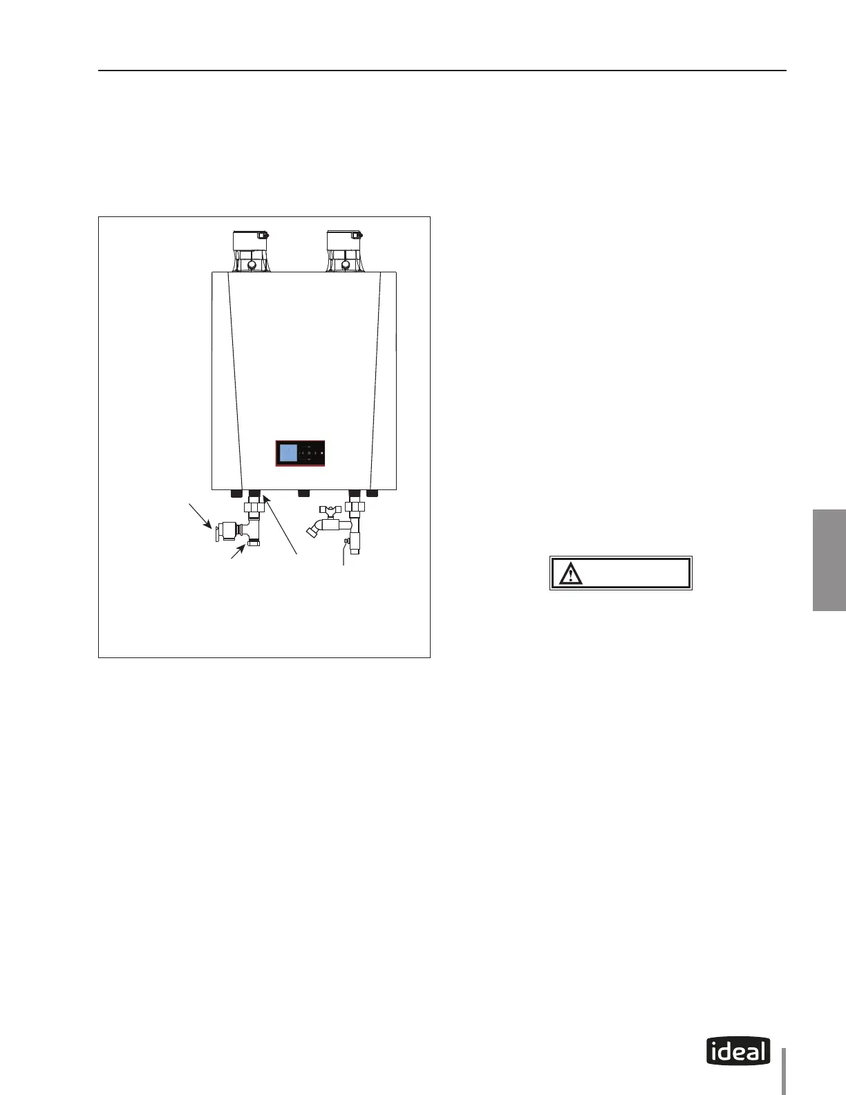
Install pressure relief valve onto the domestic piping
as shown in Fig 16 below.
Pressure relief valve
(eld supplied
Domestic connection
with Tee tting
Domestic
Hot Water
Supply
Fig. 16 - Standard Installation of the
Domestic Pressure Relief Valve
5.1.2 Pressure Relief Valve - Standard
Installations
The domestic water heater (if utilized) shall have a
eld supplied pressure relief valve installed within 6”
[152mm] of the DHW hot outlet connection with the
relief valve spindle installed in the vertical position.
The domestic water heater (if utilized) requires a eld
supplied pressure relief valve identied with the ASME
V or HV symbol and set to relieve at or below 150 psi
[10 bar] of domestic water pressure and a minimum
relieving capacity of 199,000 Btu/hr with 3/4” NPT
threads. For safe operation of the domestic water
heater, the relief valve must not be removed from its
designated location of installation or plugged.
1. The EXALT is not supplied with a 150 psi [10bar]
pressure relief valve and must be piped using a
pressure relief valve connected as shown in Fig. 16
on page 27
2. To avoid potential water damage to the surrounding
area or potential scalding hazard due to the
operation of the relief valve, the discharge piping:
• Must be connected to the discharge outlet of
the relief valve and directed to a safe place of
disposal.
• Length should be as short and direct as
possible. The size of the discharge line should
not be reduced, maintain the same size as the
outlet of the relief valve.
• Should be directed downward towards the oor
at all times. The piping should terminate at least
6 inches [152mm] above any drain connection
to allow clear visibility of the discharge.
• Should terminate with a plain end, not with a
threaded end. The material of the piping should
have a serviceable temperature rating 250°F
[121°C] or greater.
• Should not be subject to conditions here
freezing could occur.
• Should not contain any shut-o valves or
obstructions. No shut o valves should be
piped between the appliance and relief valve.
WARNING
Failure to comply with the guidelines on installing
the pressure relief valve and discharge piping can
result in substantial property damage, serious
injury or death.
5.1.3 Pressure Relief Valve Discharge Piping
Pressure relief valve discharge piping must be:
• Made of material serviceable for temperatures
of 250ºF or greater.
• Directed so that hot water ows away from all
persons.
• Directed to a suitable place for disposal.
• Installed so as to allow complete draining of the
pressure relief valve and discharge line.
 Loading...