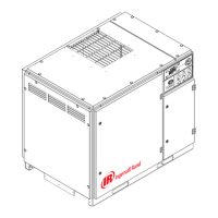
INTELLISYS OPTION
13
KEY
CON Controller, INTELLISYS
CPT Transformer, control
EDV Valve, electric drain
E–STOP Button, emergency stop
FU Fuse
M Contactor (main)
1M Coil, motor starter
OL Overload, motor starter
1SV Valve, solenoid (load) N.C
3SV Valve, solenoid (blowdown) N.O
10SV Valve, solenoid (line / sump) N.C
RST Remote start
(Optional)
RSP Remote stop
(Optional)
CFO Common fault output
PORO Power out restart (Optional)
2ATT Temperature sensor
3APT Pressure sensor
NOTES
1. Approved fused disconnect or circuit breaker per code
requirements must be provided by customer.
2. Dashed lines represent wiring by customer.
3. Sizing of electrical components not supplied by Ingersoll Rand is
the responsibility of the customer and should be done in
accordance with the information on the compressor data plate
and local electrical codes.
4. Unit will not restart automaticlly after power outage, except with
additional PORO option.
5. Circuit shown in normal position de–energized.
6. All wiring to be in accordance with local codes.
http:/air.ingersollrand.com
UP6 15, UP6 20, UP6 25, UP6 30

 Loading...


