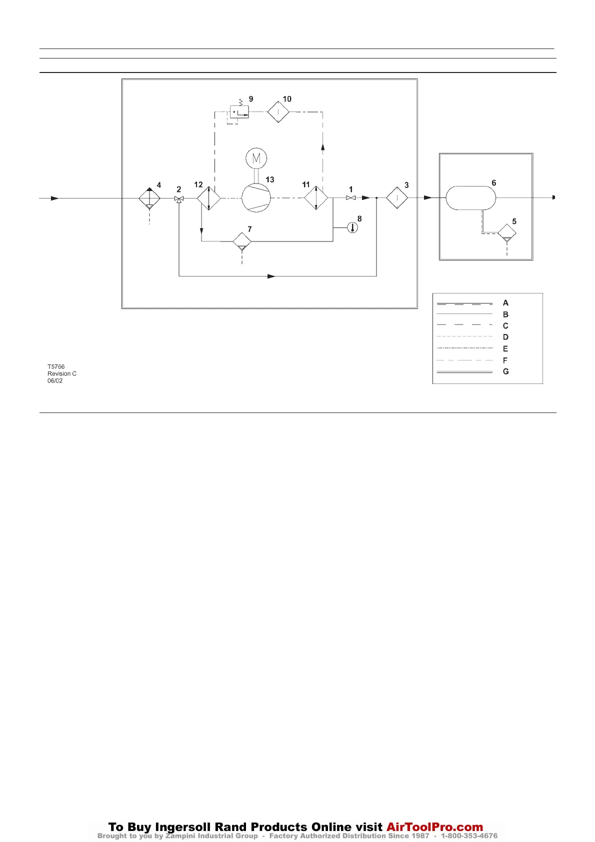
ELECTRO – PNEUMATIC CONTROL AND INSTRUMENTATION DIAGRAM
KEY
1 Valve, isolation
2 Valve, three way bypass
3. Filter, air
4Moisture separator
5. Valve, autodrain
6 Receiver, air
7. Valve, drain
8. Indicator, dew point colour
9 Valve, expansion
10 Filter, refrigerant
11.Condenser
12 Evaporator
13 Refrigerant compressor
AAir/Coolant
BAir
C Coolant
D Condensate
E Component boundary
F Refrigerant
G Option
DRYER OPTION
43
http:/air.ingersollrand.com
UP6 15, UP6 20, UP6 25, UP6 30
 Loading...