EasyManuals Logo

Ingersoll-Rand UP6 20 HP User Manual

Ingersoll-Rand UP6 20 HP
226 pages
To Next Page IconTo Next Page
To Previous Page IconTo Previous Page
Page #20 background imageLoading...
Page #20 background image
INTELLISYS OPTION
18
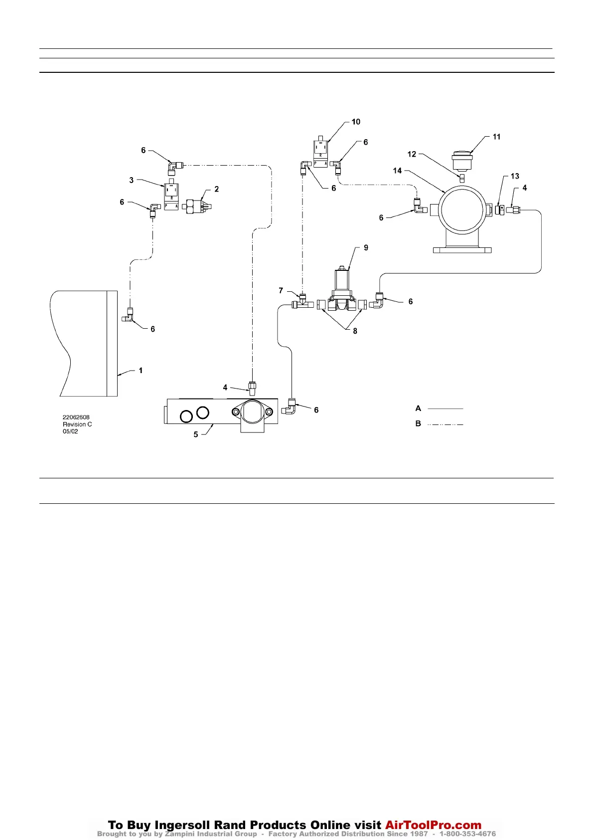
INTELLISYS CONTROL AND INSTRUMENTATION DIAGRAM
KEY
1. Tank, separator
2. Transducer, pressure
3. Valve, solenoid (Line / Sump)
4. Connector
5. Combination block
6. Elbow
7. Tee, male run
8. Reducer bushing
9. Valve, solenoid (Blowdown)
10.Valve, solenoid (Load)
11.Indicator air filter
12.Nipple
13.Adaptor
14.Intake valve assembly
NOTES:
A. Tubing 3/8 inch
B. Tubing 1/4 inch
UP6 15, UP6 20, UP6 25, UP6 30
http:/air.ingersollrand.com

Table of Contents

Questions and Answers:

Question and Answer IconNeed help?

Do you have a question about the Ingersoll-Rand UP6 20 HP and is the answer not in the manual?

Ingersoll-Rand UP6 20 HP Specifications

General IconGeneral
BrandIngersoll-Rand
ModelUP6 20 HP
CategoryAir Compressor
LanguageEnglish

Related product manuals