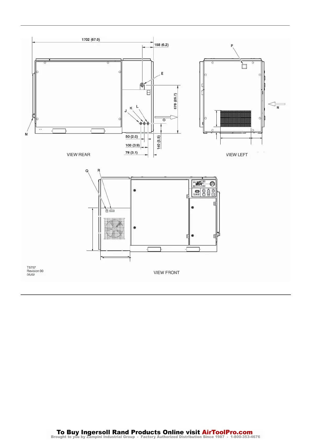
BASE MOUNTED UNITS
KEY
A Pre filter
B Compressor and cooling air intake
C Starter box
D Cooling air exhaust
E 1.00” BSPT air discharge
E 1.00” NPT air discharge
F Customer power inlet
G Fork lift openings
Fork lift hole covers must be installed after unit is in place to
reduce noise and ensure proper cooling of package)
H Button, emergency stop
I Primary compressor service door
J 0.25 inch BSPT moisture separator drain
K 0.25 inch BSPT dryer drain
L 0.25 inch BSPT air filter drain
M 1.00 inch NPT plug
N Dryer air inlet
O Dryer air exhaust
P Filter restriction indicator
Q Dryer On/Off switch
R Dew point indicator
413.5
596.3 (23.5)
165
600
317.3 (12.5)
49
DRYER OPTION
40
UP6 15, UP6 20, UP6 25, UP6 30
http:/air.ingersollrand.com
 Loading...