Heatsink Clip Load Metrology
R
Thermal/Mechanical Design Guide 69
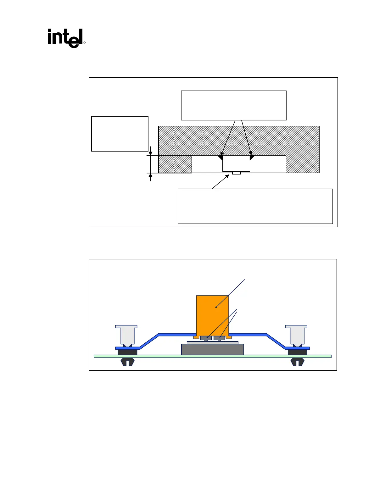
Figure 25. Load Cell Installation in Machined Heatsink Base Pocket (Side View)
Figure 26. Preload Test Configuration
Load Cells (3x)
Preload Fixture (copper
core with milled out pocket)
Wax to maintain load cell in position
during heatsink installation
Height of pocket
~ height of
selected load cell
Load cell protrusion
(Note: to be optimized depending on assembly stiffness)
 Loading...
