Appendix A: POST Code LED Decoder Intel® Server Board S5500WB TPS
Revision 1.3
Intel order number E53971-004
88
Appendix A: POST Code LED Decoder
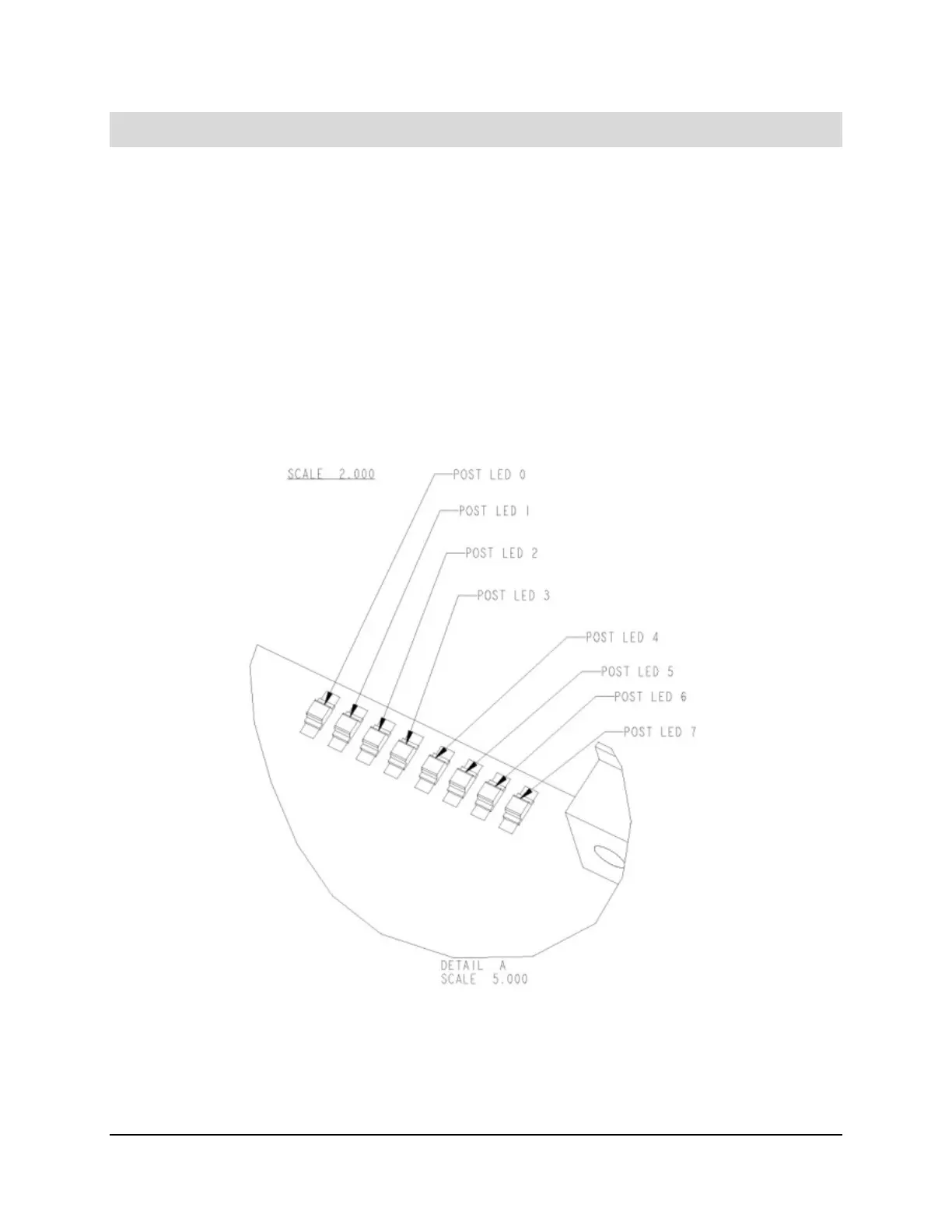
During the system boot process, the BIOS executes several platform configuration processes,
each of which is assigned a specific hex POST code number. As each configuration routine is
started, the BIOS displays the POST code on the POST code diagnostic LEDs found on the
back edge of the server board. To assist in troubleshooting a system hang during the POST
process, the diagnostic LEDs can be used to identify the last POST process to be executed.
Each POST code is represented by the eight amber diagnostic LEDs. The POST codes are
divided into two nibbles, an upper nibble and a lower nibble. The upper nibble bits are
represented by diagnostic LEDs #4, #5, #6, and #7. The lower nibble bits are represented by
diagnostics LEDs #0, #1, #2, and #3. If the bit is set in the upper and lower nibbles, then the
corresponding LED is lit. If the bit is clear, then the corresponding LED is off.
The diagnostic LED #7 is labeled as “MSB” (Most Significant Bit), and the diagnostic LED #0 is
labeled as “LSB” (Least Significant Bit).
Figure 33. Diagnostic LED Placement Diagram

 Loading...


