Design and Environmental Specifications Intel® Server Board S5500WB TPS
Revision 1.3
Intel order number E53971-004
76
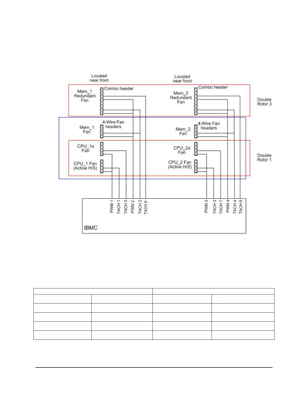
The following tables show a basic location of the fan connectors on the board. The first line is
the silk screen name of the connector; the second is the PWM signal name; the third is the Tach
#; and the forth is the reference description. The last is the signal name associated with the fault
LED signal.
Figure 28: Location of Fan Connectors
Table 52. Fan Connector Location & Detail
CPU 1 Memory 1
FAN_CPU1 FAN_CPU1A FAN_MEM1 FAN_MEM1R
PWM_CPU1 PWM_CPU1 PWM_MEM1 PWM_MEM1
Tach 1 Tach 5 Tach 2 Tach 2 & 6
J8E1 J8J4 J8J3 J9E1
LED_Fan_Fault_CPU1 LED_Fan_Fault_CPU1A LED_Fan_Fault_MEM1 LED_Fan_Fault_MEM1R

 Loading...


