EasyManuals Logo
Home>Intel>Server Board>S5500WB

Intel S5500WB User Manual

Intel S5500WB
116 pages
To Next Page IconTo Next Page
To Previous Page IconTo Previous Page
Page #76 background imageLoading...
Page #76 background image
Connector / Header Locations and Pin-out Intel® Server Board S5500WB TPS
Revision 1.3
Intel order number E53971-004
62
Pin Signal Name Pin Signal Name
7
Vsync
8
GND
9
Hsync
GND
11
KEY
12
VIDEO_IN_USE signal
13
DDC_SDA
14
GND
15
DDC_SCL
16
+5V
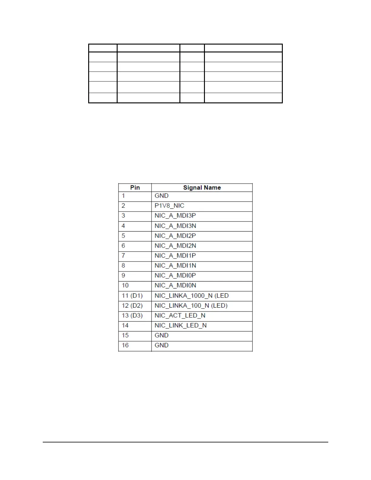
7.4.3 NIC Connectors
The server board provides two stacked RJ-45 / 2xUSB connectors side-by-side on the back
edge of the board (J8A2, J9A1). The pin-out for NIC connectors are identical and are defined in
the following table.
Table 40. RJ-45 10/100/1000 NIC Connector Pin-out (J8A2, J9A1)

Table of Contents

Questions and Answers:

Question and Answer IconNeed help?

Do you have a question about the Intel S5500WB and is the answer not in the manual?

Intel S5500WB Specifications

General IconGeneral
BrandIntel
ModelS5500WB
CategoryServer Board
LanguageEnglish

Related product manuals