Design and Environmental Specifications Intel® Server Board S5500WB TPS
Revision 1.3
Intel order number E53971-004
78
• Tcontrol offset Temperature = -2° C
• Pos_hyst = 0° C
• Neg_hyst = 3° C
Those parameters in turn set the following:
• Upper = - CPU PECI Tcontrol + Tcontrol offset
• Lower = - CPU PECI Tcontrol + Tcontrol offset – 3C
9.2.2 Memory Temperature Sensor
DDR3 cooling requires thermal throttling to protect memory from overheating. The Intel
®
Server
Board S5500WB supports both DDR3 UDIMM and DDR3 RDIMM. SPD temperature sensor on
DIMM is anticipated to be available on all DDR3 RDIMM but not for non-ECC UDIMM, so open
loop thermal throttling and closed loop thermal throttling are supported.
• Static open loop thermal throttling: The system does not change any of the control
registers in the processor during runtime. OLTT control registers are configured by BIOS
MRC and remain fixed after post.
• Static closed loop thermal throttling: The system does not change the control
registers for a closed loop in the processor during runtime. CLTT control registers are
configured by BIOS MRC.
For advanced implementation with dynamic OLTT and CLTT, refer to the VR_Hot Sensor in
VR11.1.
9.2.3 Board Temperature Sensor
For rack-based systems or those systems that do not have a front panel temp sensor, the board
is enabled to use a board-mounted, industry standard “TMP75” type temp sensor. This part is
on the IBMC two-wire serial SENSOR bus. The use of digital parts removes calibration and
placement location issues imposed by the alternate analog type sensors.
9.2.4 Thermals Sensor Placement
The SMBUS based temp sensors are placed such that the ambient air temp can be measured.
Placement near hot components and or downstream of hot components (including chassis-
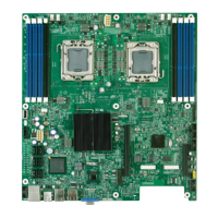
based hot spots) is avoided. The following figure shows the sensor placement on the Intel
®
Server Board S5500WB.
 Loading...
