Configuration Jumpers Intel® Server Board S5500WB TPS
Revision 1.3
Intel order number E53971-004
46
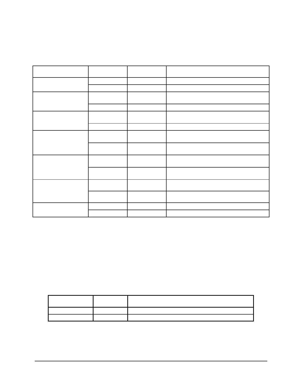
Table 16: Server Board Jumpers (J1B5, J1C2, J1C3, J1B4, J6A3, J6A2)
Jumper Name Jumper Position
Mode of
Operation
Note
1-2 Normal IBMC GPIO[1] is pulled HIGH. Default position. J1B5: BMC Force
Update jumper
2-3 Update IBMC GPIO[1] is pulled LOW.
1-2 Normal ICH10R INTRUDER# pin is pulled HIGH. Default
position.
J1C2: Password Clear
2-3 Clear Password ICH10R INTRUDER# pin is pulled LOW.
1-2 Normal ICH10R GPIO [55] is pulled HIGH. Default
position.
J1C3: BIOS Recovery
Mode
2-3 Recovery ICH10R GPIO [55] is pulled LOW.
1-2 Normal ICH10R RTCRST# pin is pulled HIGH. Default
position.
J1B4: CMOS Clear
2-3 Clear CMOS
Settings
ICH10R RTCRST# pin is pulled LOW.
1-2 Internal Internal connector will override if both connectors
are used.
J6A3: Video Master
2-3 External External connector will override if both
connectors are used.
1-2 Disabled Default J7A2: ME Firmware
Force Update
2-3 Enabled
1 – 2 DCD to DTR Data Carrier Detect J6A2: Serial Interface
3 – 4 DSR to DTR Data Set Ready
6.1.1 Force IBMC Update (J1B5)
When performing a standard BMC firmware update procedure, the update utility places the
BMC into an update mode, allowing the firmware to load safely onto the flash device. In the
unlikely event the BMC firmware update process fails due to the BMC not being in the proper
update state, the server board provides a BMC Force Update jumper (J1B5) which will force the
BMC into the proper update state. The following procedure should be followed in the event the
standard BMC firmware update process fails.
Table 17. Force IBMC Update Jumper
Jumper Position
Mode of
Operation Note
1-2 Normal IBMC GPIO[1] is pulled HIGH. Default position.
2-3 Update IBMC GPIO[1] is pulled LOW.
1. Power down and remove the AC power cord.
2. Open the server chassis. See your server chassis documentation for instructions.
3. Move jumper from the default operating position, covering pins1 and 2, to the enabled
position, covering pins 2 and 3.

 Loading...


