Functional Architecture Intel® Server Board S5500WB TPS
Revision 1.3
Intel order number E53971-004
36
The PEWIDTH is pulled up to 3.3 V Aux on the baseboard and grounded, if necessary, by the
riser. The baseboard provides an inverter and voltage level translator before passing this signal
to the IOH.
3.13.3 Slot 1 PCI Express* x8 Connector
Slot 1 provides a PCI Express* x4 bus on an x8 connector, if provided, for use in a 2U chassis
that uses LP boards without risers. Although it is feasible to use the IOM at the same time, it
would require 2U chassis back panel changes.
3.13.4 I/O Module Connector
Mezanine connectors are provided to support the various I/O modules, both the older Gen 1 I/O
modules supported by Intel
®
Server Board S5000PAL and newer, double-wide Gen 2 I/O
modules supported by the Intel
®
Server Board S5520UR are supported on the Intel
®
Server
Board S5500WB.
The Intel
®
I/O Expansion Module is also required to inform the IOH of the Intel
®
I/O Expansion
Module Bus usage, PEWIDTH bit 1 is to be used for this.
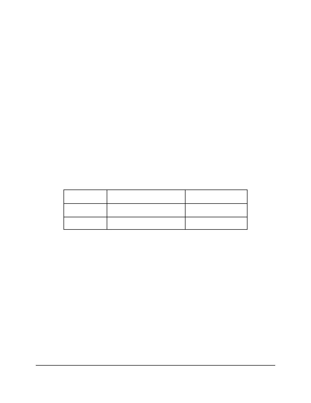
Table 12. Intel
®
I/O Expansion Module Bus PEWIDTH Bits
Intel
®
I/O
Expansion Module
Description PEWIDTH1 - Pin 2
one x8
1 x8 PCI Express* target
device
0
two x4 2 x4 target devices 1

 Loading...


