Intel® Server Board S5500WB TPS List of Figures
Revision 1.3
Intel order number E53971-004
ix
List of Figures
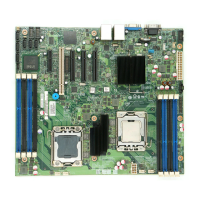
Figure 1. Intel
®
Server Board S5500WB 12V................................................................................ 4
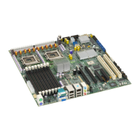
Figure 2. Intel Server Board S5500WB SSI.................................................................................. 5
Figure 3. Intel
®
Server Board S5500WB Components (both SKUs are shown) ..........................6
Figure 4. Rear Panel Connector Placement: ............................................................................... 8
Figure 5. Baseboard and Mounting holes .................................................................................... 9
Figure 6. Connector Locations................................................................................................... 10
Figure 7. Primary Side Height Restrictions ................................................................................ 11
Figure 8. Secondary Side Height Restrictions ........................................................................... 12
Figure 9. Intel
®
Server Board S5500WB Functional Block Diagram .......................................... 14
Figure 10. Lifting the load lever of ILM cover............................................................................. 17
Figure 11. Removing the socket cover ......................................................................................18
Figure 12. Installing processor................................................................................................... 18
Figure 13. Package Installation/Remove Feature...................................................................... 19
Figure 14. Installing/Removing Heatsink .................................................................................... 20
Figure 15. Intel
®
QPI Link............................................................................................................ 21
Figure 16. Memory Channel Population ....................................................................................23
Figure 17. Installing Memory......................................................................................................24
Figure 18. Mirroring Memory Configuration ............................................................................... 26
Figure 19. Integrated BMC Hardware ......................................................................................... 33
Figure 20. S5500WB SMBUS Block Diagram ........................................................................... 43
Figure 21: Jumper Blocks (J1B5, J1C2, J1C3, J1B4, J6A3, J6A2, J7A2) .................................. 45
Figure 22: 5-V Standby Status LED Location ............................................................................. 67
Figure 23. Fan Fault LED Locations ........................................................................................... 68
Figure 24. System Status LED Location ..................................................................................... 69
Figure 25. DIMM Fault LEDs Locations ...................................................................................... 72
Figure 26. Rear Panel Diagnostic LEDs ..................................................................................... 73
Figure 27: Thermal Zones...........................................................................................................75
Figure 28: Location of Fan Connectors....................................................................................... 76
Figure 29. Fans and Sensors Block Diagram ............................................................................. 77
Figure 30: Temp Sensor Location............................................................................................... 79
Figure 31. Unified Retention System and Unified Backplate Assembly..................................... 80
 Loading...
