18
LBK System Series| Instruction manual v1.2 SET 2021 |SAF-UM-LBKBus-en-v1.2|© 2020-2021 Inxpect SpA
3. Get to know LBK System Series
3.2 LBK System Series control units
3.2.1 Control units supported
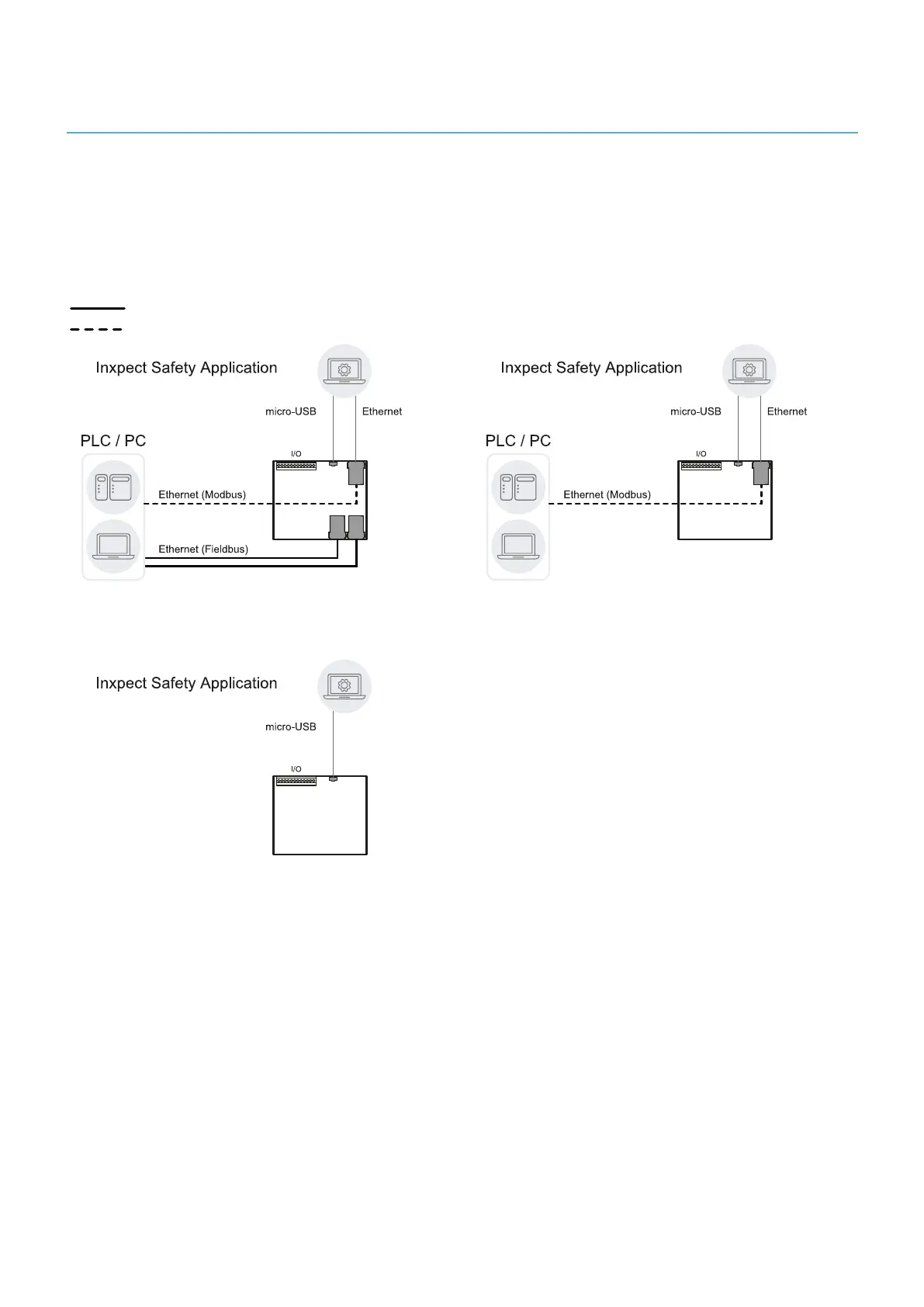
The LBK System Series supportsthree different control units. The main difference among them are the
connection ports and therefore the communication interfaces available:
l ISC-B01: two Ethernet ports for Fieldbus, an Ethernet port for system configuration and Modbus
communication and a micro-USB port
l ISC-02: an Ethernet port for system configuration and Modbus and a micro-USB port
l ISC-03: a micro-USB port
Safe
Unsafe
ISC-B01 communication architecture.
ISC-02 communication architecture.
ISC-03 communication architecture.
3.2.2 Functions
The control unit performs the following functions:
l Collects information from all the sensors via CAN bus.
l Compares the position of detected motion with the set values.
l Deactivates the dedicated safety output when at least one sensor detects motion in the detection field.
l Deactivates all the safety outputs if a failure is detected in one of the sensors or the control unit.
l Manages the inputs and outputs.
l Communicates with the Inxpect Safety application for all configuration and diagnostic functions.
l Allows dynamically switching between different configurations.
l Communicates with a safety PLC through the Fieldbus connection (if available)
l Communicates and exchanges data through Modbus protocol (if available)
 Loading...
