Parameter Min Max Default value
System configuration and status PS2v4 1
65535
146
Sensors information PS2v4 1
65535
148
Sensor 1 detection status PS2v4 1
65535
150
Sensor 2 detection status PS2v4 1
65535
152
Sensor 3 detection status PS2v4 1
65535
154
Sensor 4 detection status PS2v4 1
65535
156
Sensor 5 detection status PS2v4 1
65535
158
Sensor 6 detection status PS2v4 1
65535
160
Fieldbus endianness Big Endian, Little Endian Big Endian
Settings > Modbus Parameters
Modbus Enable Enabled, Disabled Enabled
Listening port 1 65534 502
8.5 Digital input signals
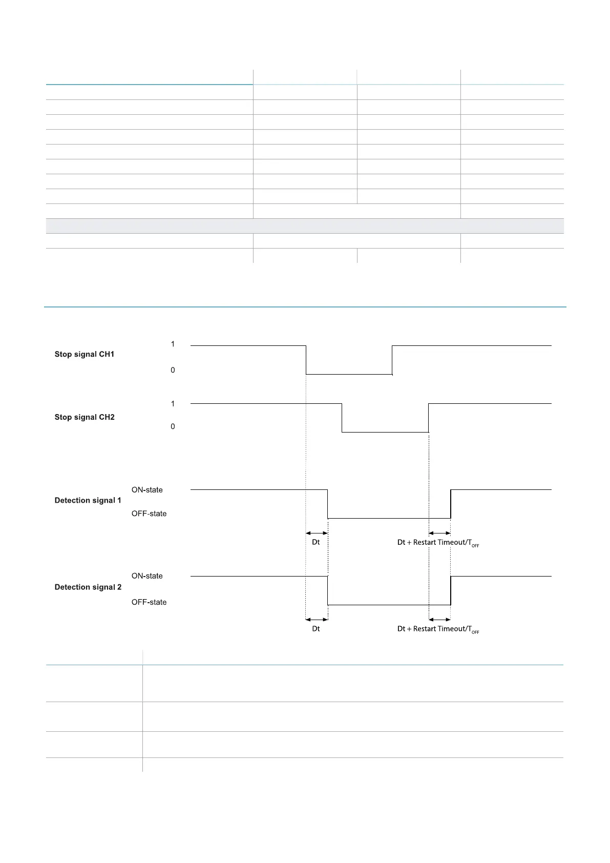
8.5.1 Stop signal
Part Description
Detection signal 1
Detection signal 2
Both deactivate on the falling edge of, at least, one of the two input channels of the input
signal. They remain in OFF-state as long as one of the two input channels remains to the
low logic status (0).
Stop signal CH1
Stop signal CH2
Interchangeable channel. Both channels must go to low logic level (0) to set Detection
signal 1 and Detection signal 2 to OFF-state.
Diff Less than 50 ms. If the value is greater than 50 ms, the diagnostic alarm starts and the
system deactivates the safety outputs.
Dt Activation delay. Less than 5 ms.
8. Technical references
LBK System Series| Instruction manual v1.2 SET 2021|SAF-UM-LBKBus-en-v1.2|© 2020-2021 Inxpect SpA
101
 Loading...
