56
LBK System Series| Instruction manual v1.2 SET 2021 |SAF-UM-LBKBus-en-v1.2|© 2020-2021 Inxpect SpA
5. Sensor position
5.4 Calculation of position for sensor height ≤ 1 m
5.4.1 Introduction
The formulas for calculating the optimum position of the sensor for sensors with installation heights less than or
equal to 1 m (3.3 ft) are reported as follows.
WARNING! Define the optimum sensor position according to the risk assessment requirements.
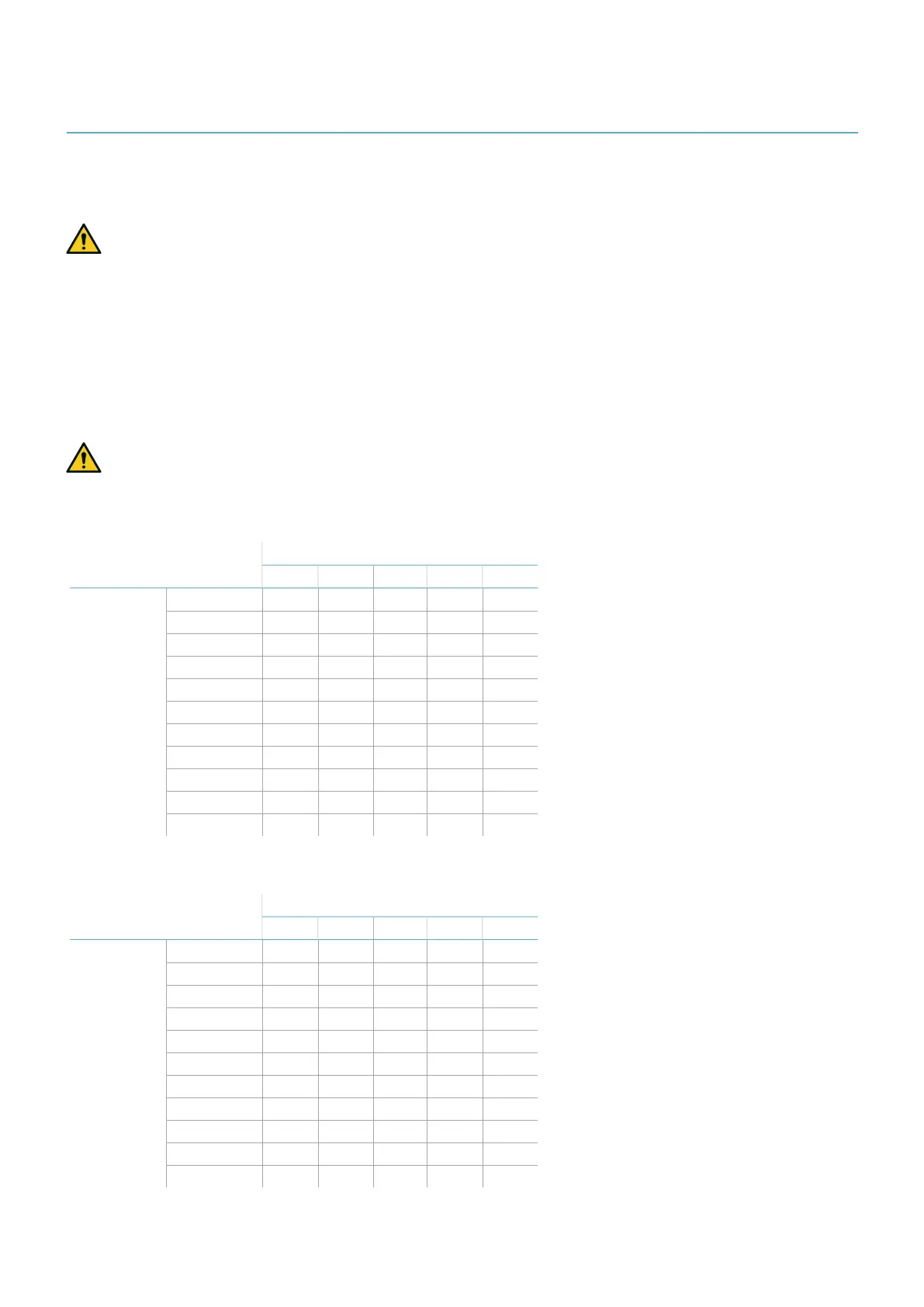
5.4.2 Overview of possible installation configurations
The configurations with possible heights (h) and inclinations (α) are presented as follows:
l 1 = Configuration 1: the field of view of the sensor never intersects the ground
l 2 = Configuration 2: the upper portion of the field of view of the sensor never intersects the ground
l 3 = Configuration 3: the upper portion and the bottom portion of the field of view always intersect the
ground
l X = Configuration not possible
WARNING! With configurations not listed in these tables or marked with an “x”, safety functions are
not guaranteed.
110° field of view
Installation
configuration
α (°)
-20 -10 0 10 20
h (cm | in)
0 | 0 x x x 2 1
10 | 3.9 x x x 2 1
20 | 7.9 x x 2 2 1
30 | 11.8 x x 2 2 x
40 | 15.7 x x 2 2 x
50 | 19.7 x 2 2 2 x
60 | 23.6 3 2 2 x x
70 | 27.5 3 2 2 x x
80 | 31.5 3 2 2 x x
90 | 35.4 3 2 2 x x
100 | 39.4 3 2 2 x x
50° field of view
Installation
configuration
α (°)
-20 -10 0 10 20
h (cm | in)
0 | 0 x x x 1 1
10 | 3.9 x x x 1 1
20 | 7.9 x x 2 1 x
30 | 11.8 x x 2 x x
40 | 15.7 x x 2 x x
50 | 19.7 x 3 2 x x
60 | 23.6 x 3 2 x x
70 | 27.5 x 3 2 x x
80 | 31.5 3 3 2 x x
90 | 35.4 3 3 2 x x
100 | 39.4 3 3 2 x x
 Loading...
