Maintenance
Engine
98 9831/0650-3 98
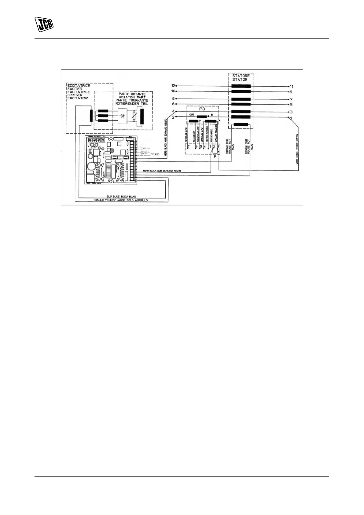
Figure 77.
Regulator Setup
Selection of the sensing scale takes place directly according to the connection on the power terminal board;
additional settings can be made with 4 trimmers (VOLT, STAB, AMP and Hz) and 3 jumpers (50/60Hz, JP1
and JP2).
Terminals 4, 5, 6, 7 and 8 of connector CN1 are used for voltage sensing.
Trimmers
The trimmers are enabled by the software from the Configuration Menu. If they are not enabled, they do not
perform any function.
The Volt trimmer allows adjustment from about 70V to about 140V or from about 140V to about 280V.
The Stab trimmer adjusts the dynamic response (statism) of the alternator under transient conditions.
The Hz trimmer allows a variation up to - 20% with respect to the nominal speed value set by jumper 50/60 (if
it is active) or from box 50/60 of the Configuration Menu (at 50Hz the threshold can be calibrated from 40Hz
to 50Hz, at 60 Hz the threshold can be calibrated from 48Hz to 60Hz). The Amp trimmer adjusts the excitation
overcurrent protection intervention threshold.
Excitation Overcurrent
The DSR regulator is equipped with an excitation (main rotor) winding temperature estimator.
An estimate of the temperature is memorised in real time (and can be read) at location 45. The progress of
the temperature is of the exponential type.
Through parameter 22 or the AMP trimmer, it is possible to define a limit (which involves intervention of alarm
5) to the excitation voltage and therefore to the temperature.
The function of this alarm is not only to signal an excessive temperature, but it also has an active function
in reducing the cause. In fact, an adjustment ring takes control of the voltage generated when the threshold
set is exceeded.
This reduces the voltage to the point of reducing the excitation current by a value compatible with the ability
of thermal dissipation of the machine.
 Loading...